JS II
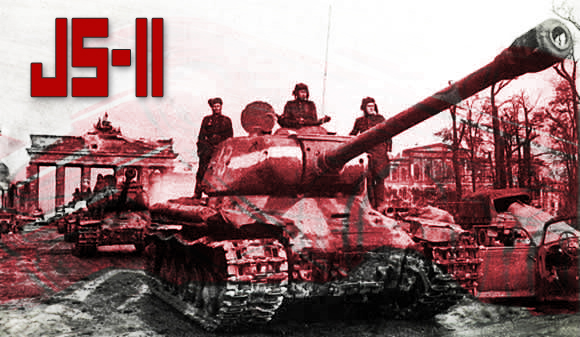 The IS-2 tank first saw combat in the spring of 1944 and were assigned to separate heavy tank regiments, normally of 21 tanks each. These regiments were used to reinforce the most important attack sectors during major offensive operations. Tactically, they were employed as breakthrough tanks. Their role was to support infantry in the assault, using their large guns to destroy bunkers, buildings, dug-in crew-served weapons, and other ’soft’ targets. They were also capable of taking on any German AFV if the need arose. Once a breakthrough was achieved, lighter, more mobile T-34s would take over the exploitation. The IS-2 weighed about the same as a German Panther, and was lighter than the German heavy tanks, the Tiger series. It was slightly lower than both. A major weakness was the two-part ammunition, which slowed
 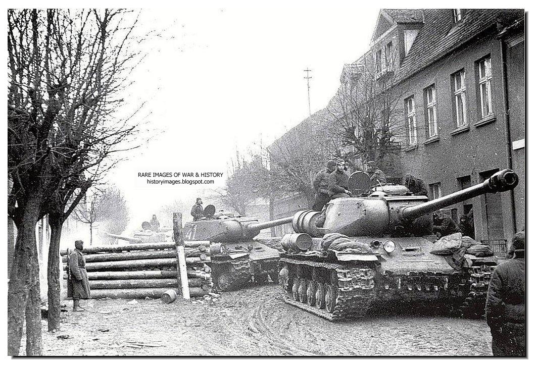 the rate of fire considerably. A second weakness was the very limited ammunition supply of only 28 rounds. This was the price paid by the small size of the design. One of the IS-2’s most notable engagements took place during the fighting in August 1944 to establish a bridgehead over the river Vistula around the town of Sandomierz.. This was the first time the IS-2 had come up against the fearsome Tiger II. During the engagement on August 13, the 71st Independent Heavy Tank Regiment’s eleven IS-2s blocked an attack by fourteen Tiger IIs of the 105th Heavy Panzer Regiment.
![]()
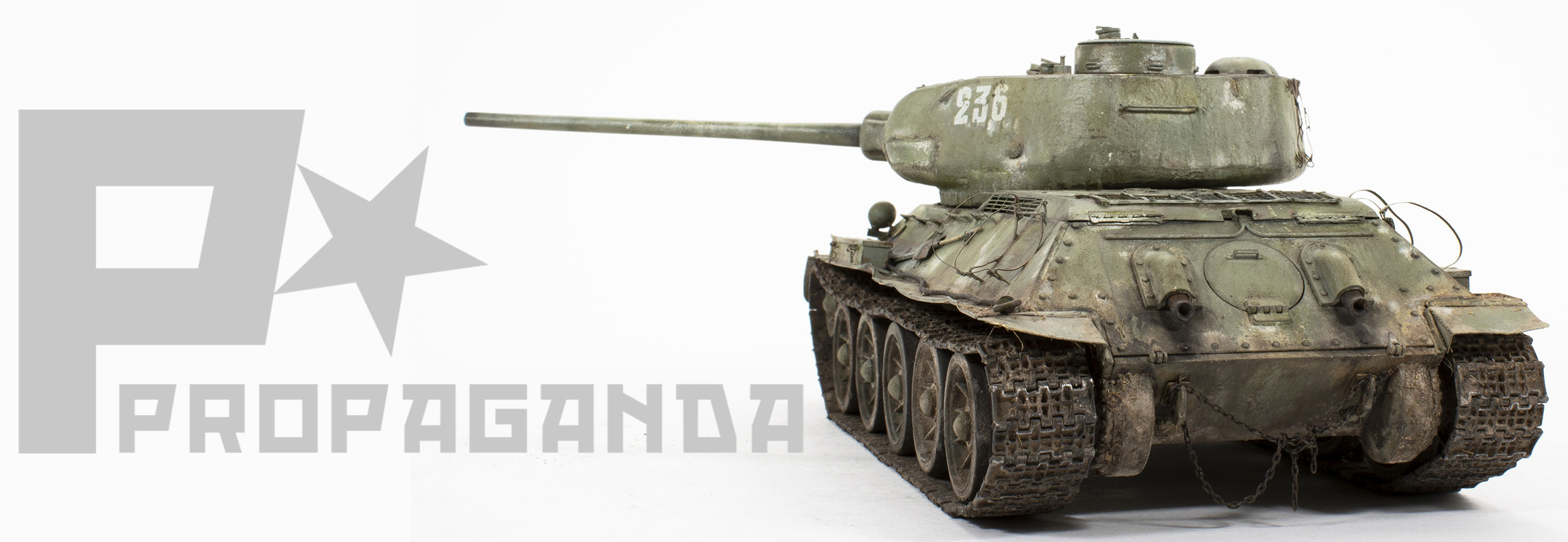
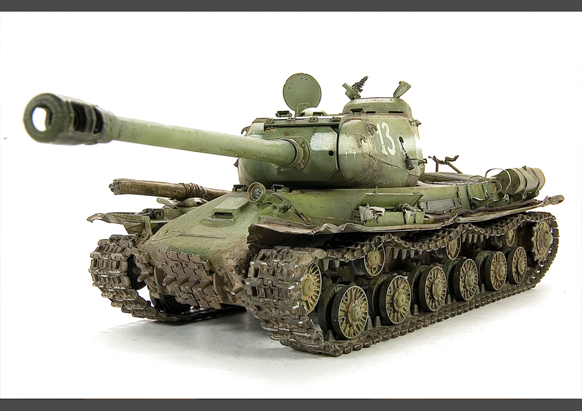
It would be an understatement to say that the Tamiya JS-II is a nice kit directly out of the box; as a matter of fact it is an excellent kit as built from the box. So what, you might ask, would possess me to add just about every conceivable aftermarket item available to this project? Partially the answer is to be found in how I conceived of the final presentation. I knew that I wished to portray as battle weary vehicle as seen during the final months of the war; torn fenders, dented auxiliary fuel tanks and torn brackets would be necessary to convey the image. Therefore, a good helping of brass would be just what was needed to achieve the effects. In addition, a nice set of Fruilmodel tracks would help to achieve realistic weight and sag as so often seen on Soviet vehicles.

|

|

|

|

|

|

|

|

|

|

|

|

|

|
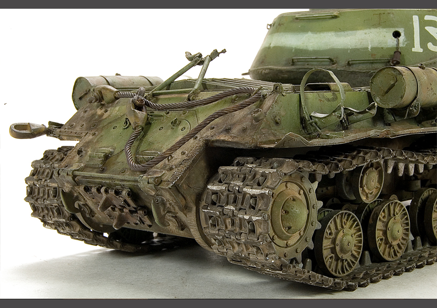
It’s no secret that using aftermarket sets can help to achieve realistic scale and finish, but they can also present a lot of extra work for the modeler. In the case of the JS-II, Tamiya has manufactured the fenders attached to the hull, so it is necessary to remove the original plastic fenders in order to install the replacement photo etch fenders. To begin the removal process I scribed the fenders along the hull line using the tip of a new scalpel. Once I had a definite, and deep line I was able to wiggle the fenders back and forth until they snapped off. A little light sanding along the hull removed any remnants and I was ready to proceed.
Next, I turned my attention to the photo etch. Because of their larger size and related stresses I chose to solder the all of the photo etch connections. The same is true for the auxiliary fuel tanks as their shape will pull apart seams held only with CA glues. And although somewhat delicate in nature neither the Aber fenders nor the Voyager fuel cells posed any difficulties during construction or soldering.
Once I had the fenders constructed it was time for a little test fit, and it was during the affixing of the Aber fenders to the hull that I ran into some difficulties. To the rear of the vehicle the fenders fix as intended; snug against the hull. Toward the front, however, while the hull of the vehicle contours the fenders maintain a perfectly straight line. The resulting gap becomes quite apparent at about the second support rib and only increases toward the front. I checked and rechecked the alignment and soldering of the fenders looking for any mistakes, but found none. The fact that this issue occurred on either side only affirmed to me that the problem was in the fender’s design. Ok, what to do?
I decided the best (and easiest?) approach was to take advantage of the rough cast texture and simply add a little more bulk and width to the edges of the hull were it meets the fenders. Small bits of Milliput were applied to the hull in order to slowly “re-cast” the shape so that the support ribs and fenders would make contact. After the Milliput had dried a liberal coating of Mr. Surfacer 500 was applied to the area to blend it with the surrounding area. Finally, a light coating of Mr. Surfacer 500 was brushed, and then stippled with a stiff brush to recreate the cast texture.
|
|

|

|

|

|

|

|

|

|

|
The turret also received a little extra detailing by adding thin strips of Evergreen rod along the welds. The strips were washed with liquid cement to soften the plastic, and then new weld details were imprinted using the back of my Xacto blade. Once again a light brushing of Mr. Surfacer served to blend the new welds with the surrounding areas.
The remainder of the construction was for the most part straightforward. My biggest challenge was simply keeping track and sorting through the numerous instruction sheets that I had laid upon my work desk. By now the beast was really taking shape, and the new brass bits were really making for an impressive show; I’m quite the sucker for shinny things. During this time I also constructed the excellent Fruilmodel tracks. Included in the Fruilmodel package is thin wire to be used to pin the links together, however, I find this wire to be to flexible and prefer to use .18 gauge brass wire instead.
I had been looking forward to painting this beast from the outset. Over the past months I have been exploring some of the principals of light, shadow, and color tone as expressed though the “color modulation” theory. Matter of fact my initial attempt, a 1:48th Marder III was included as the cover feature of the September, 2009 issue of Fine Scale Modeler. I began the painting process with an overall primer coating of Mr. Surfacer 1000. The primer is particularly important when working with multi-media projects such as this.
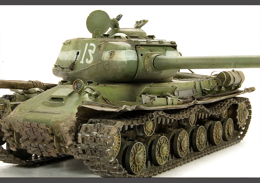
The initial base color is intentionally bright mix created from Tamiya XF-13 J.A. Green, XF- 67 Nato Green, and XF-4 Yellow Green. In this case, the Yellow Green is my lightening color that I will be using though out the process to add highlights and interest to the details. I used a small mask made from cut cardstock for quick, crisp edges between panels and features. I feel that adding these sharp demarcation lines between panels and features is an important element in the process which promotes a more visually interesting finish. The thing to keep in mind is that this is not a linear process, and quite a bit of back-n-forth occurs as I return to add highlights to certain features, or deepen shadows in other areas. As a final touch I added just a hint of XF-2 Flat White to my color mix and lightly misted the upper areas. This helps unify the colors a bit, but the white also begins the process of creating fading paint in the weathering steps.
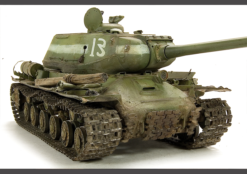
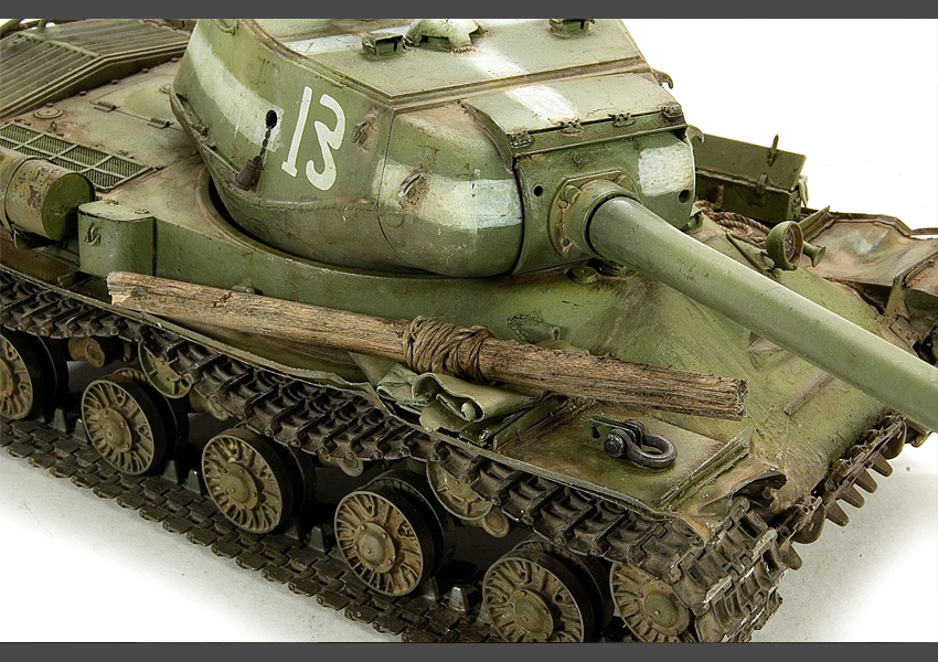
 The turret received some extra, additional attention as I prepared to paint the larger air recognition stripes. The stripes were painted with a two step process: First, I airbrushed a light, uneven base white color between the taped areas. Secondly, I removed the tape and returned with the brush to “repaint” the stripes, once again intentionally uneven to simulate the hasty, hand painted stripes so often seen in period photographs.
With the painting completed I gave the entire model a light mist of Future acrylic floor polish to seal the paint. The limited decals were applied, and then another light mist assured that everything was sealed up and ready for weathering. I began the weathering by applying MIG Productions Abteilung 502 Shadow Brown directly into all of the nooks and crannies of the vehicle. And then with a soft brush I feathered the paint and removed any heavy, unnatural accumulations. Although a somewhat subtle effect, I feel that this is an important step in creating a certain weight and depth to the final presentation.
I followed this with more artists oils, this time in the form of dot fading using MIG Productions German Ochre, Olive Green, and Faded Green. These dots are applied to a surface that has been pre-moistened with thinner, and then the dots of oil are worked into the surface using a larger, soft brush. The idea is to create subtle, tonal variation to the base color which helps to add to the visual interest of the vehicle. Once this has dried I returned once again with the oils, but this time concentrating only on the smaller lines and details using the Shadow Brown color as a pin washes. Once again, this is not a linear process so I often will return to adding more dots, then more pin washes until I have achieve an appearance that I am satisfied with.
 There always reaches a certain time during the painting process when I realize that the paints and oils have reached their functional limits; the look I am after just cannot be achieved by doing more of the same. It’s at this point that I incorporate the pigments into my weathering mix. I think of the pigments more as an extension of painting, rather than a separate material. With that thought in mind, I always dissolve my pigments in thinner and apply them wet by using a small brush. I generally begin the applications in the corners and vehicle recesses, similar to how I applied my initial Shadow Brown color, then with each application I slowly work my way to the panel centers. I find that I have great control using this technique as the pigments only go where I place them. From time to time I will use a soft, dry brush to soften and edge or
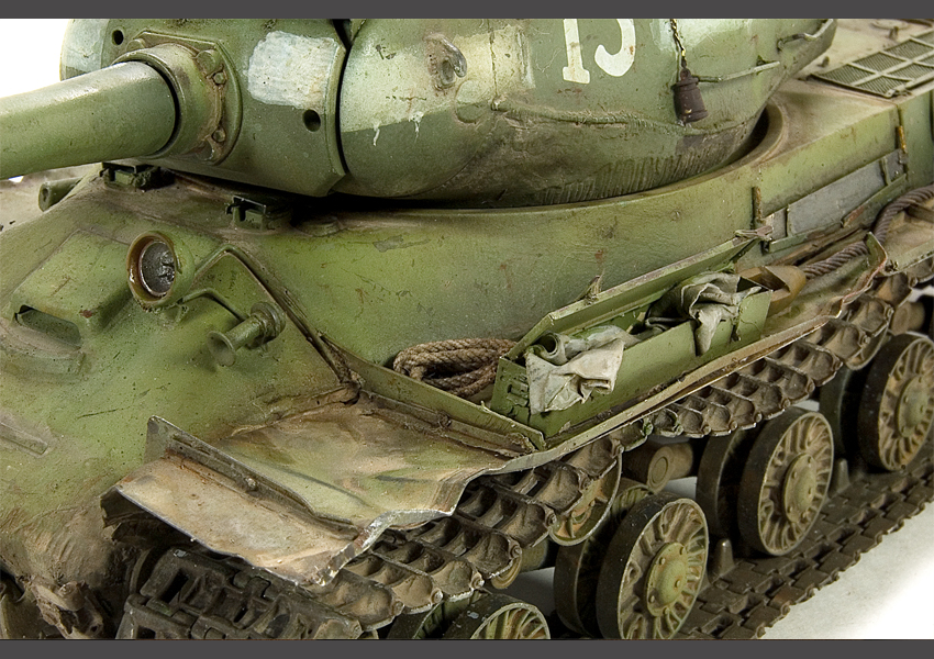
 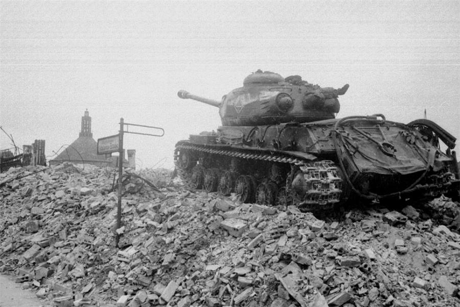 remove extra accumulations from an area. Of course, to be natural in appearance the modeler must capture the messy, random nature of mud and dirt. As a final step I used a brush and my finger to flick small droplets and splashes to the appropriate areas of the vehicle where such accumulations would naturally occur. The small un-ditching log on the fender was made from a small section of wooden doweling painted quickly washed with brown and grey artists oils. The small rag hanging from the tool box is made from Milliput.
I find myself at the end of this article wondering what conclusions or advice might be drawn from my experience. Obviously, the amount of aftermarket materials that I used its own unique challenges and it is difficult to relate all the trials and tribulations that occurred in this short article. So with this in mind I guess that I have two thoughts that I would like to share: First, using all sorts of photo etch and aftermarket item available is not necessary to achieving a wonderful result. Secondly, it’s nice to know that there is all of this wonderful stuff available to use when you decide to use it.
      |


Hi Rick i have been constantly viewing and using your website for tips and as a reference for a little over a year now and i feel that it has certainly ‘tightened’ my skills. i would just like to write my sincere thanks to you for creating this website.
Regards Chip Wimbledon, London UK