For the Motherland
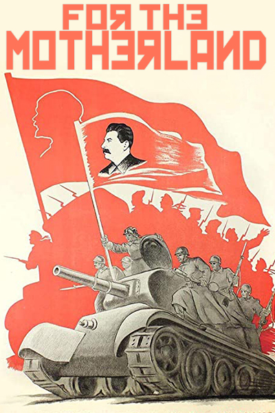 When it comes to armored warfare and the history of WWII, the T34 (and it’s variants) deserve an extra thick chapter any book that chronicles defeat of Nazi Germany – and afterward. In 1942, Adolf Hitler is reported to say to his military staff at his Wolf’s Lair headquarters in East Prussia, “If I had known that there were so many of them, I would have had second thoughts about invading!”
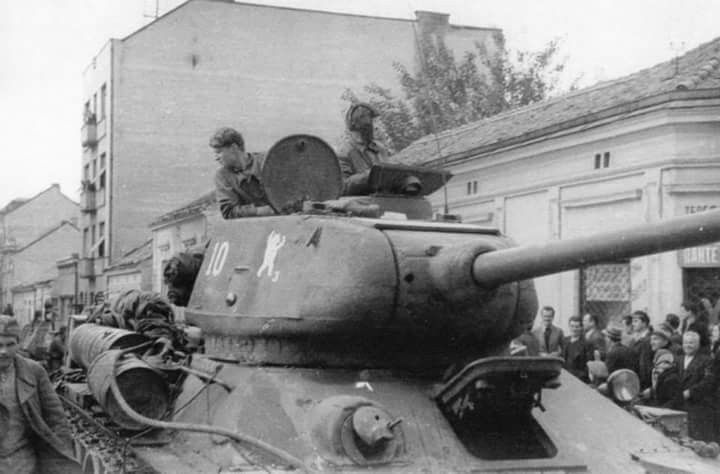
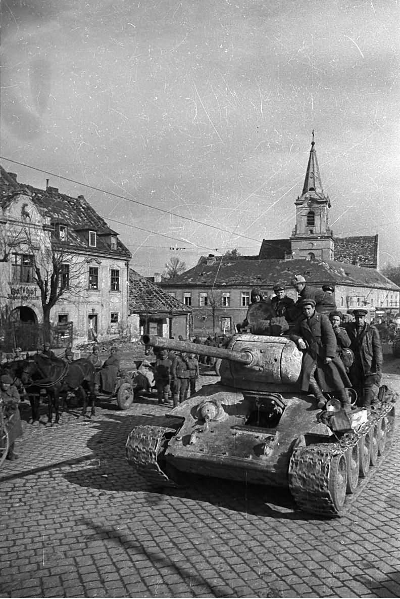
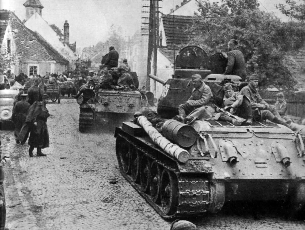
The “them” he was referring to was the Soviet Red Army T-34, the now-iconic tank that had come as such a nasty surprise to the Germans in the summer of 1941. The T34, and it’s variants continued to be a thorn in the side of the German’s throughout the war, ultimately rolling onto the streets of a shattered Berlin in April of 1945.
Drs. Matthew Hughes and Chris Mann in their 2002 work The T-34 Russian Battle Tank noted, “The presence of the T-34/76 in 1941 proved to be a rude shock for the Germans. Compared to other Soviet tanks, the T-34 was able to take on and destroy the best of the German panzers. In various modifications—and despite some setbacks—the T-34 held its own until the war’s end in the ruins of Berlin in 1945.”
Initial T34 production models sported the 76.2mm gun as its’ main weapon which had a real hitting power by the standards of the day. Perhaps, more importantly, was its radical sloping armor that gave superior protection while keeping overall weight down. Its diesel engine and Christie suspension system provided superb cross-country performance as well.
 Realizing their disadvantage, Germany set about an aggressive program of regaining the advantage, upgrading the panzer forces with armament upgrades to existing the of Pz. III and Pz IV variants, and the introduction of a newly designed Pz. V, Panther, and later King Tiger, who design are clearly influenced by the T34 distinctive sloped armor.
Of course, a punch must be responded by a counter-punch, and by 1943 the Russians realize that the T34’s 76.2 main gun is becoming ineffective against the up-armored German panzers. In response, a program was begun to up-gun the T34. After tests, the ZiS-S-53 (85mm) and chosen to go into production as the new main weapon. For expedited production reasons, it was ordered to be equipped upon existing T34 chassis design. In the end, the turret required some modifications to accommodate the larger 85mm main gun, and heavier armor were added to the same basic chassis. “Indeed, the T-34/85 makes the strongest claim of any of the T-34 family for the title of the best all-around tank of any stage of the war,” wrote Hughes and Mann. “The design has also proved to be remarkably durable. It remained the Soviet main battle tank until the mid-1950s, and the Bosnian Serbs were still using T-34/85s during the fighting in the former Yugoslavia in the 1990s. Such longevity in a modern major weapon is unprecedented.”
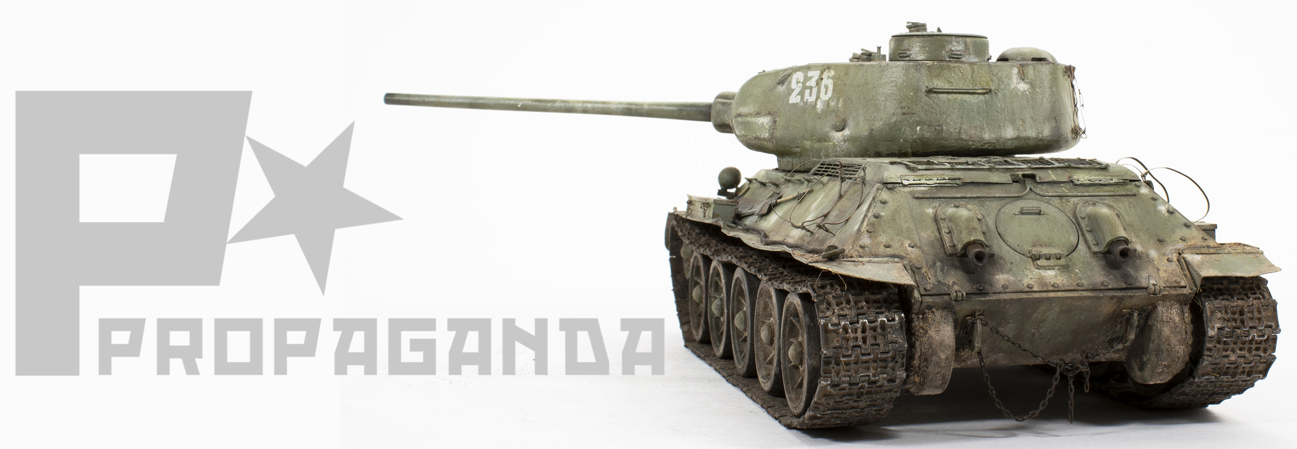
 When this project came to be the only direction was to “build a T34”. Now that’s wide open…and great. That is until I realized that choosing which variant I was going to do of this iconic tank was going to be a bigger challenge than I expected. What to do? Should I do an early version or late? Should it be with the 76mm or 85mm gun? Of the nearly 40,000 vehicles produced during the war should I find a unique, eye-catching example; or one-of-the-many? The T34 world is very big, indeed. In the end, I decided to portray a more-or-less “run of the mill” T34/85 as would be common during the spring of 1945. However, being “common” doesn’t mean that I can’t have fun with the project; test my skills using aftermarket upgrades and produce an interesting finish.
Before I get started, let me give you a bit of an overview of the base kit and a few thoughts and intentions for this project. First, as the article progresses you may notice a lack of kit build shots. This is partially due to the fact that the kit is relatively easy and straightforward to build and I felt that it might become redundant (boring?) if the body of the article was a recipe narrative of “I glued this part to that part”. Modelers with basic skills shouldn’t find any difficulties with this model if built straight from the box. That said, what I hope will to accomplish is to show areas that can include adjustments, alterations, improvements, and additions to the basic kit, along with an explanation of what I did and why.
In terms of finishing, I wanted to change up my normal routine, even if only slightly, by using different brands of paint and fully exploring the power within the artist’s oils. I’ll get into these specifics as the article unfolds. Overall, I chose to portray a veteran tank with wear and damage operating in the spring of 1945, its’ winter white was nearly worn away.
It’s an armor kit, and guess what? Road wheels. In this instance along with the normal cleaning of the molding seams and sprue points, I also wanted to create a worn, used appearance on the rubber adding divots and blemishes using my trusty #11 blade. While these effects can be subtle, it’s the cumulation of these small enhancements that help to create the overall tone of the model. Photo etch details can add exceptional touches of realism to your models, but using it also brings an added level of complexity to the project. 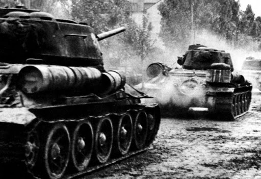 First, there is a balance of two (or more) sets of direction on the workbench. Then, there is the decision of when to use the kit part, or when the use of the photo-etch replacement is the better alternative. And finally, there is a base level of skill, proficiency, and probably most importantly, confidence that the use of photo-etch requires.
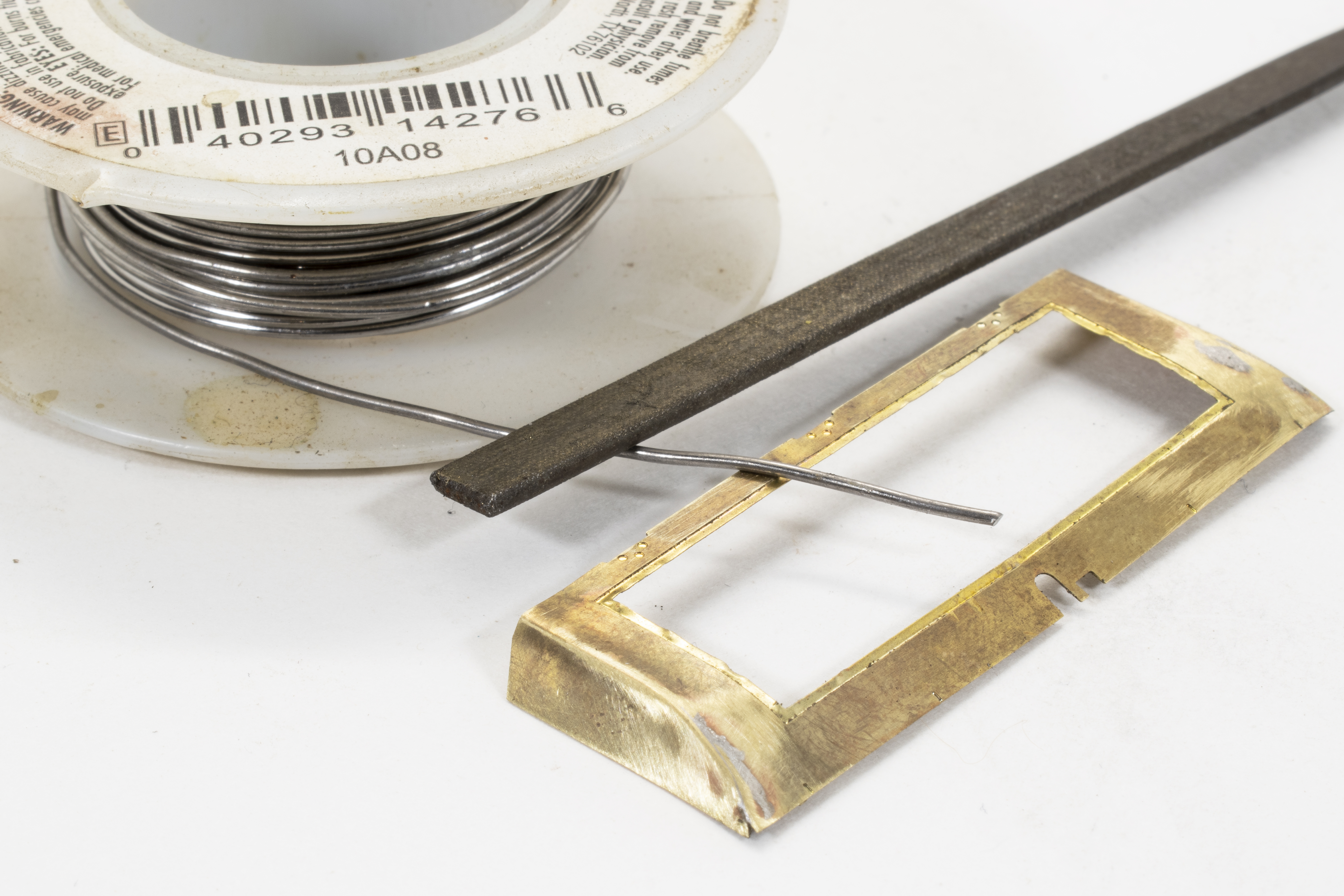
Once you’ve decided to take the photo-etch plunge, one of the most important investments you can make is a good photo-etch bending tool. These tools are available from a number of companies, look for one of the finest quality you can afford. This photo shows one of the fender stowage boxes is bent to shape using my bending tool pried upward using a straight-edge razor. A file is used to remove unwanted sprue burs.
Photo-etch parts can be attached using two methods; the first being the use of CA glue, the other being soldering. Each of these methods has it’s purpose and use, but on larger parts such as the storage boxes solder is the better option as it provides a strong bond. Soldering also allows for further manipulation (read damage) that I’ll be doing in the later steps without fear of everything falling apart. The lid of the storage box has raised strengthening ribs. The photo-etched part includes location indicators on the inside of the lid part. Pressing these areas using a ballpoint pen and using a thin piece of cardboard underneath (rather than on a hard surface) will indent the part to create the raised feature.


The photo above shows the reverse side of the same piece after pressing, now with the raised ribs. The next step for this part will be to fold down the thin edges to create the sides. To do this, I will flip the part over once again and then bend the small tabs upward, using the etch tool to securely hold the part while using the razor blade to leverage the part upward for the bend. Two storage boxes are used on the T34, one on the front left fender and the other on the right rear fender. After building the basic box shapes, including soldering both the lid and box on the inside joints, the hinges, latches, and chains are added and secured in place using a tiny amount of CA glue.
 The rear engine vent and hatch is the most complicated photo etch element of this project in that it’s large and includes curved surfaces. The payoff is that it absolutely enhances the final appearance of the model. The curved shape is dictated by the side pieces, and with a little patience and some gentle coaxing, it’s fairly easy to get the top piece to follow the side-wall contour. I used a pen, rolling it back and forth to help initiate the curve of the top piece. Even with this preliminary bending and coaxing there still is quite a bit of tension and spring within the parts. This is absolutely one of those instances where soldering is the best option to ensure a tight, permanent bond between parts. The soldering bead is done on the inside of the part so that only a small bit of clean-up or filing is required along the outside edges for the part to look perfect.
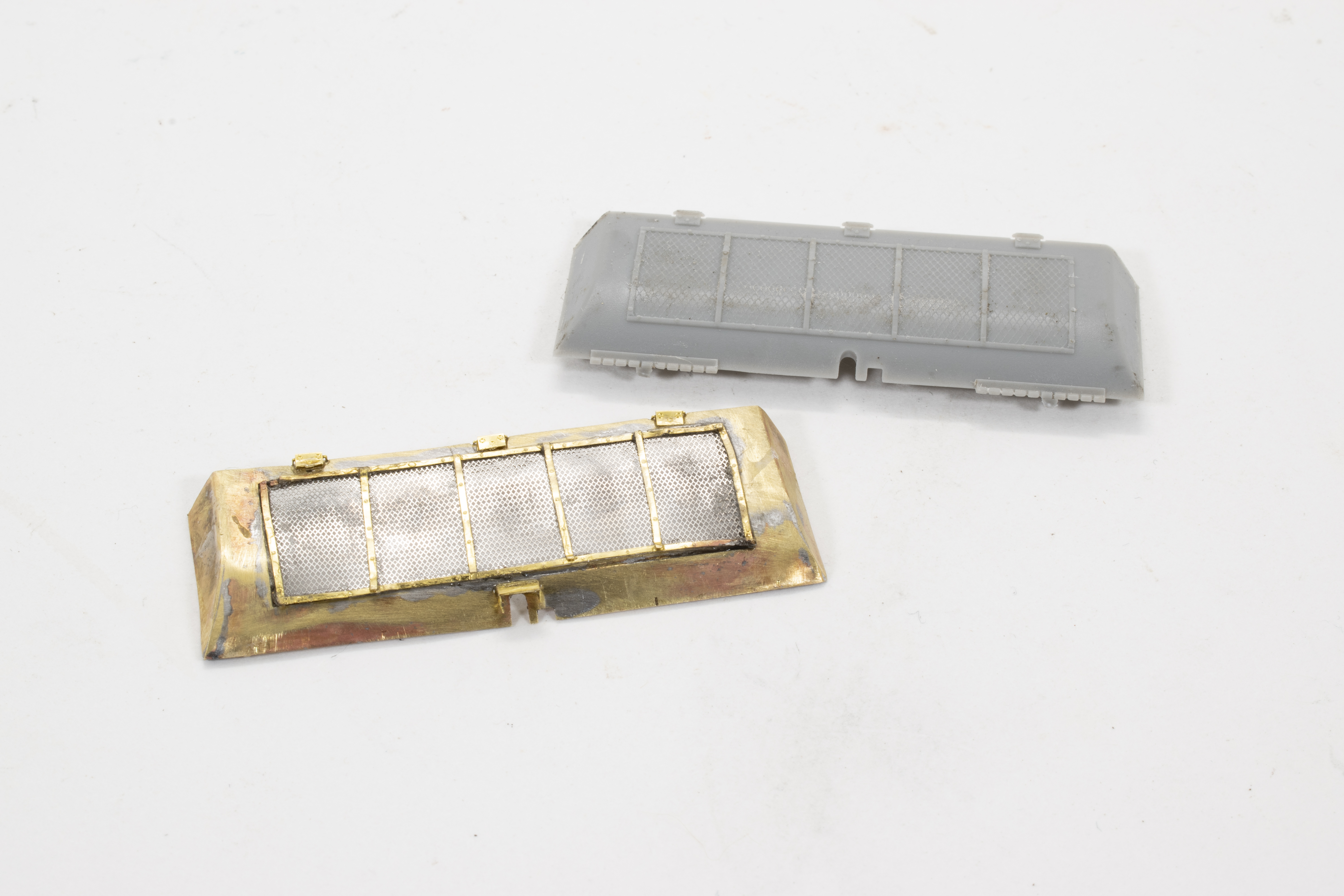 This photo clearly compares the kit part against the new photo-etched part. The solid, textured plastic screen is now replaced with a real mesh screen. The unevenness of the new screen adds a bit of lived-in character to the part. One note, the mesh of the provided photo etch screen is
very fine and the open areas are susceptible to being filled or clogged during the painting process – this happened to me. Later, during the project, you may notice that I removed the screen that you see here and replaced it with a larger weave mesh in order to eliminate the issue.
Another important point to consider when working with photo-etch is that there is a lot of time spent simply making the necessary preparations for the kit in order to accept the photo-etch details. In this case, the notches on the rear hull are locator holes intended for the kit’s external fuel 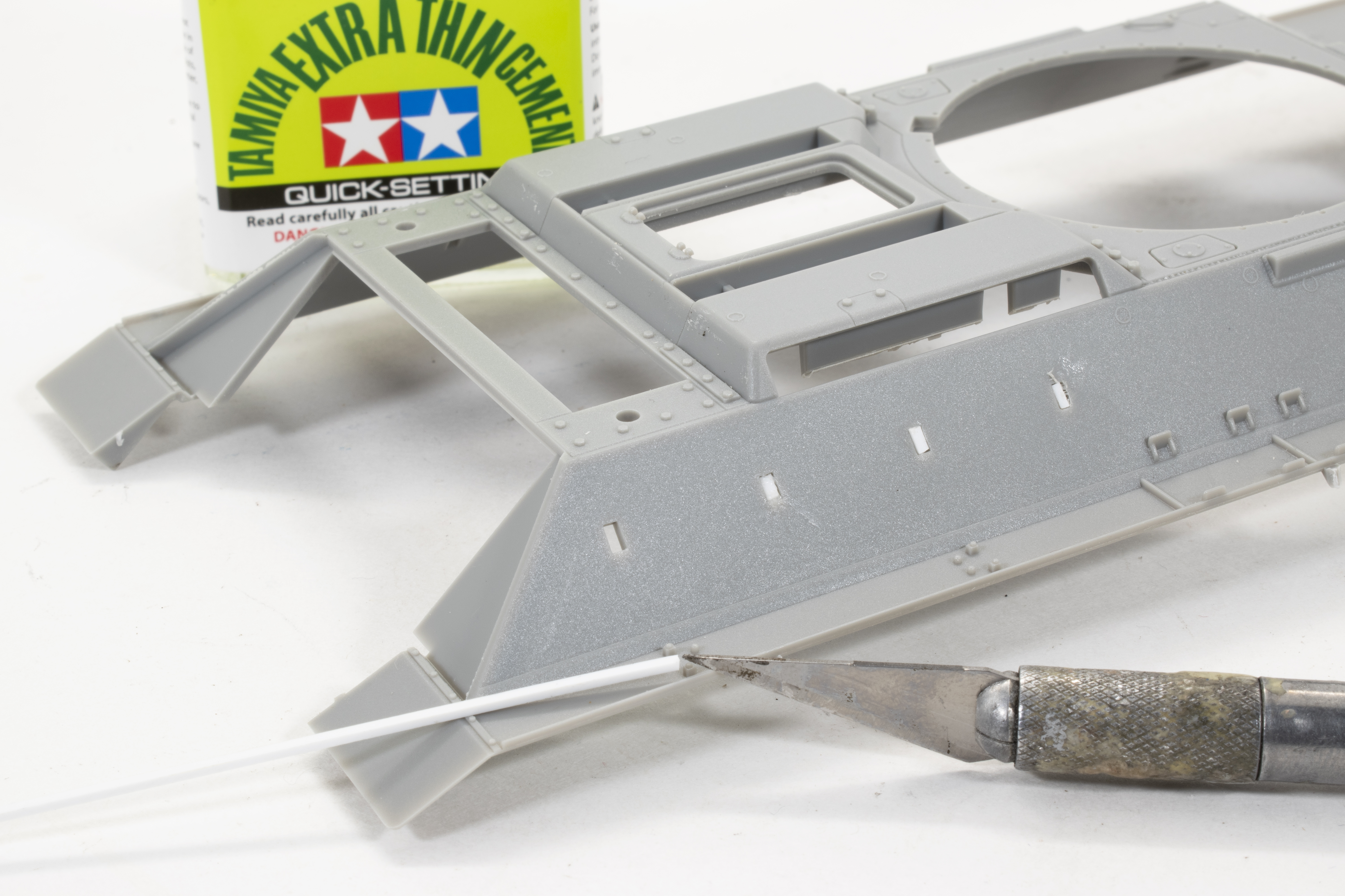 tank brackets, but since I’ll be using photo-etch replacements these holes must be filled. The quickest, easiest method for dealing with this type of issue is to first fill the hole with an appropriate size of plastic stock (Evergreen), and then finish the surface either with a bit of putty or CA sanded to remove any trace of the hole.
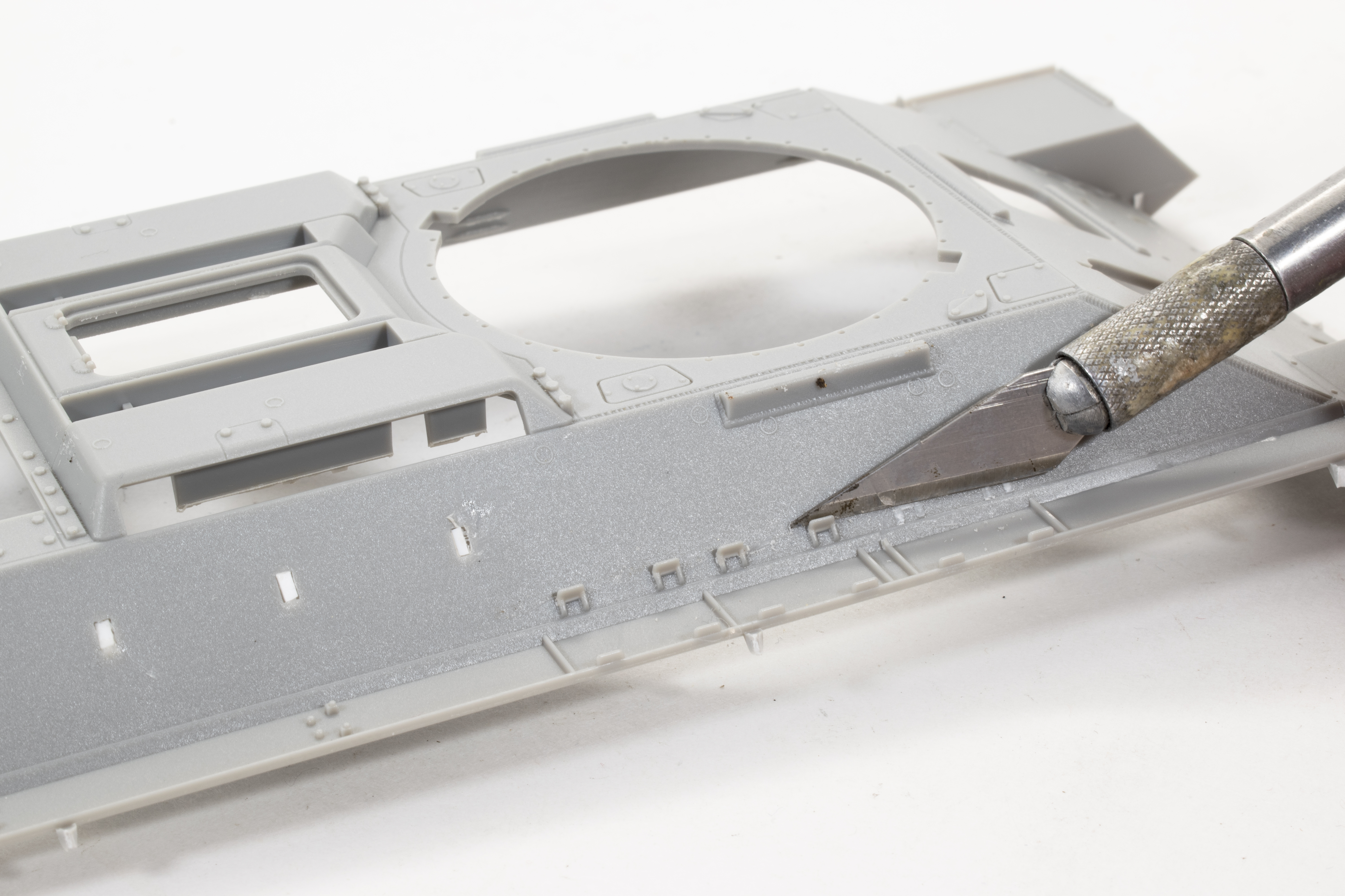
This same type of prep work is done in each of the areas where I will be adding photo-etch details. It’s at about this point that I have 3 sets of instructions spread out on my work table – one for the kit and 2 for the photo-etch – at times it can feel a bit overwhelming with all these diagrams telling me what do do. Just take a deep breath. It’s important to study all sets of instructions thoroughly so as to come up with a game plan on which items you will choose to remain as original kit parts, and which items are to be replaced or enhanced by the etch. In this photo, I am removing the brackets for the snow cleats as they will be replaced with small photo-etch brackets.
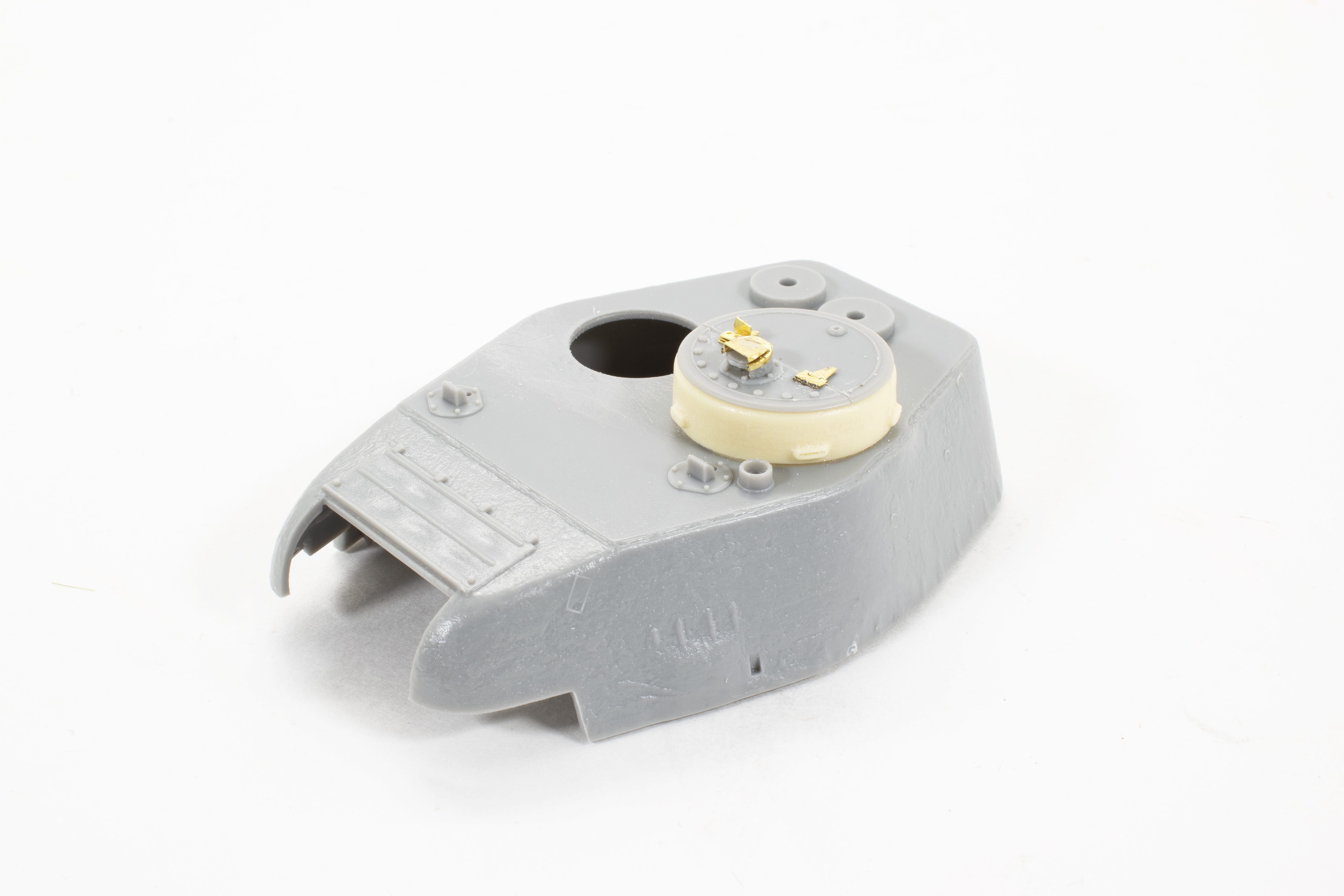 The Voyager set includes a resin replacement for the copula ring, a nice addition as it has finer detailing than the kit part. While the resin part fit perfectly into the turret hole, the hatches did require a bit of sanding. As you can see photo-etch details also replace the periscope covers and hinges.
Is there a doctor in the house? Now comes the major surgery, and as scary as this looks it is really a simple process and one that really makes a statement. The goal here is to replace the existing kit fenders with brass etch fenders. On most armored vehicles this is one of the more important upgrades that you can do, as the slight wrinkles and waves in the metal provide a very realistic appearance. Not to mention the fact that if you are portraying damaged metal fenders there is nothing more realistic than bending real metal.
The T34, in particular, is an easy surgery as the fenders are clearly defined along the hull edge. The plastic fenders are removed by scoring along 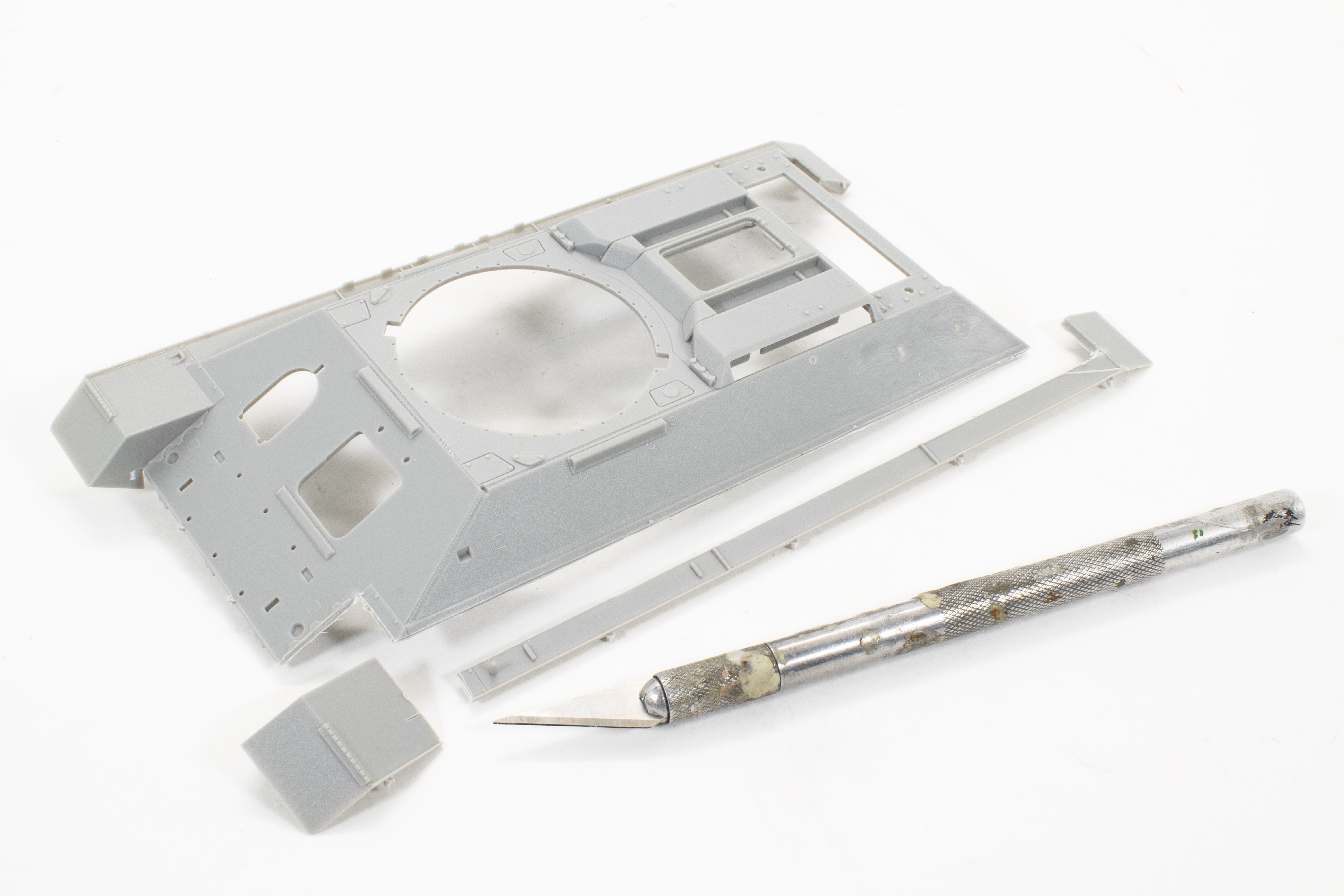 the edge of the hull and fender using my trusty #11 blade using light strokes until I achieve a depth of cut that allows me to snap off the fender. For ease, I did this in two parts removing the front fender separately. A sharp blade makes this work much easier and helps to ensure a clean-cut, making for less clean-up or fixing.
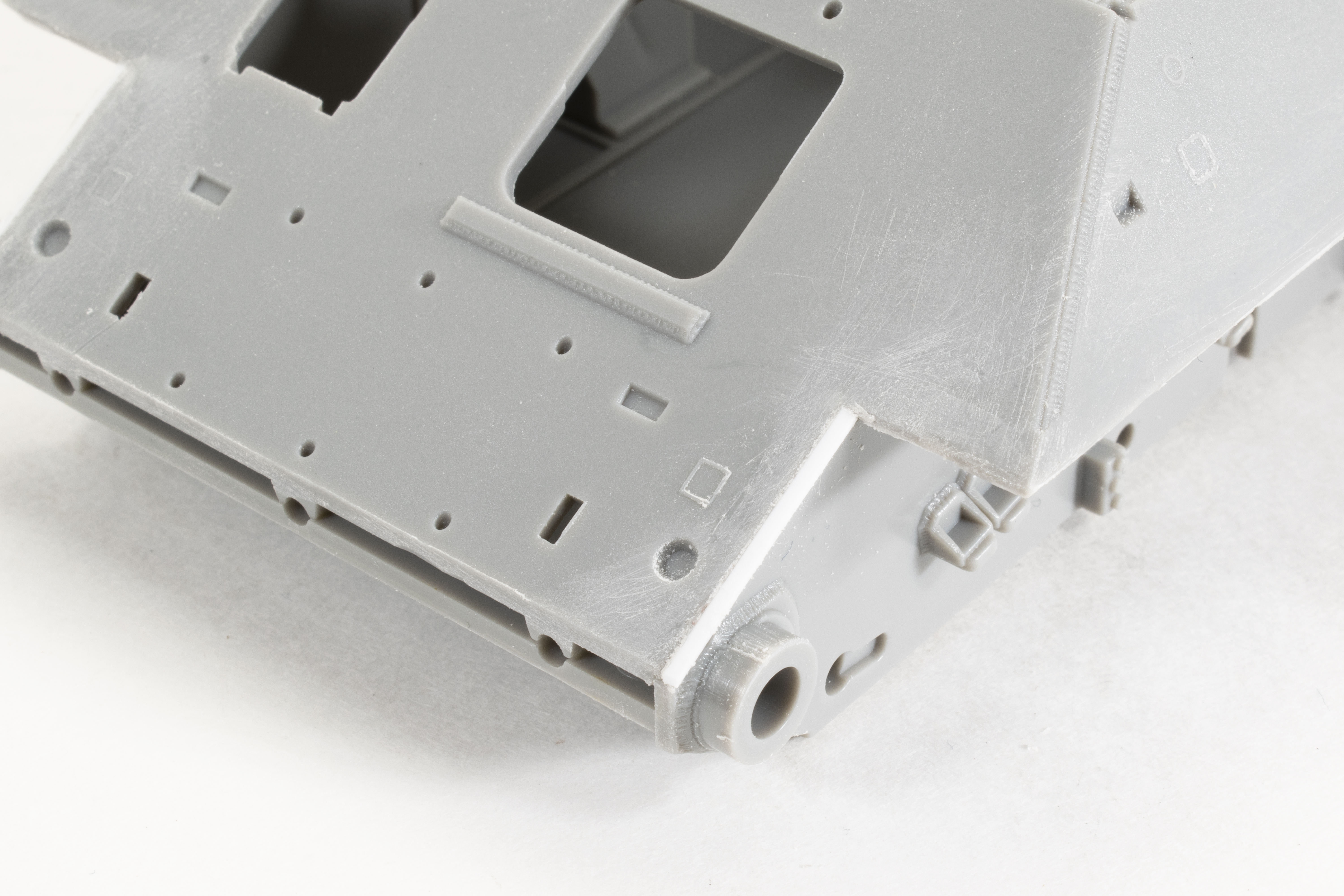
It’s not uncommon when removing plastic that gaps may be revealed, and that was the case here along the front of the hull. Once again I used an appropriate size of Evergreen strip plastic to fill the gap and then sanded the surface flush.
After all of the unwanted plastic is removed, the surfaces are sanded and clean, it’s time to get busy on the new photo etch fenders. One of the first things I notice about these fenders is that they include a very small upward profile along the outer edge. While it’s possible to, accomplish this bend with the etch as is, it is much easier to do this type of bending after first annealing the brass. Annealing is a simple technique of heating the brass, using a flame or burner, so as to “soften” the brass. You will know it has achieved the desired heat threshold when the brass either turns bright orange or darker blue color as it’s heated. It’s a quick process and you’ll need to be careful not to over-do it and burn the metal. The small outer edge of the fender is secured by my folding tool and now all I need to do is bend the fender fold the fender upward using the razor to create the upward edge.


I mentioned earlier that soldering parts was preferred, especially on larger parts. For these small fender supports, I choose to solder for no other reason than I needed them to be securely fastened so that they won’t pop off later while I’m “damaging” the fenders. I prepare the surfaces by brushing a light coat of soldering flux to the area that will receive the part. In this particular instance, I first tinned the bracket and then placed the bracket into position onto the area that I had previously added flux. Next, I will touch the bracket (while in position) with the soldering iron, re-melting the solder on the bracket which will then mate the bracket to the fender. This is a quick and clean way to attach small parts when soldering.
Before I move along past this step, let me try to clarify and define some of the soldering terminologies.
- Flux – Think of this as the oil in the skillet. It usually comes as a paste or gel that when heated bubbles and sizzles and promotes the melting of the solder. A quick tip is that the solder usually is maintained only to the fluxed area, making it possible to limit the soldering zone to very specific areas. This will make your life much easier as the more localized the solder means less excess solder to cleanup.
- Speaking of clean-up. To remove excess solder, metal files are your friend. If an area can’t be reached by a file I will use various grits of sandpaper and then usually polish the area using steel wool.
- Annealing – This is the physical process of softening the brass using heat. This can be done using a burner, lighter, or candle, just be careful not to burn through the parts. It’s really quite remarkable how pliable the brass becomes making it much easier to bend those tricky parts.
- Tinning – The process of “pre-soldering” the part or area before adding the second part. Using the fender bracket as an example, the small bracket was first brushed with flux and then solder added and melted onto the bracket. Then, then the area of the fender the bracket is to be installed is brush with flux. The tinned bracket is placed upon the fluxed area on the fender, and then the soldering iron touched to the bracket. The heat reactivates solder on the bracket, melts and adheres to the fluxed fender.


The full fenders are ready to install. The curved front and rear fender flap are separate parts, formed to shape and then soldered to make the complete fender. Looking at the curved fender you will see where I once again made use of the pen to create the raised rib along the edge. I also annealed this piece before bending just to make it a little easier to get the proper shape. This is also the stage that I’ve done a good deal of test fitting of the fender to the hull and I know that it all fits perfectly. Phew!
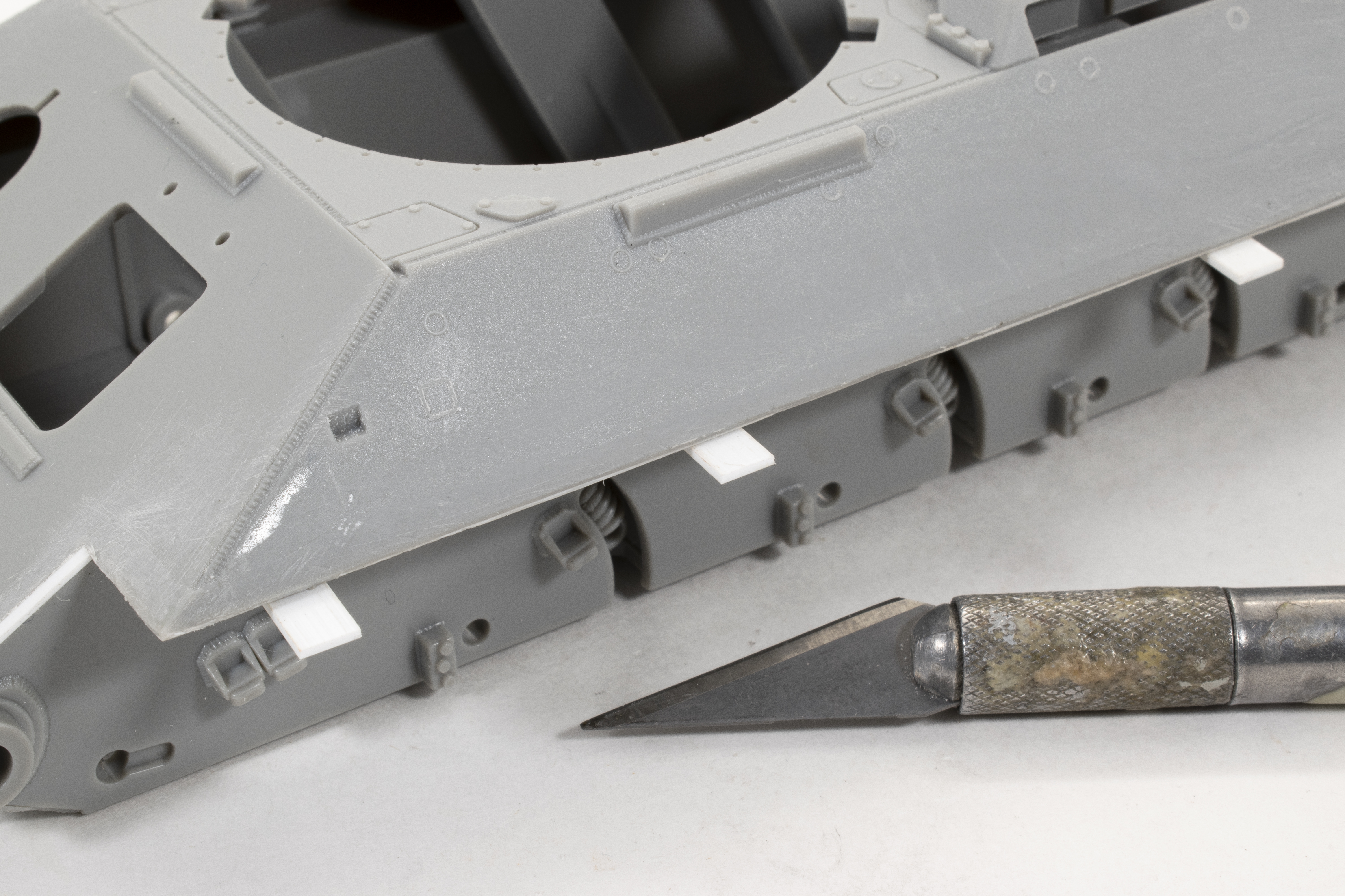 In preparation for adding the fenders, I glue a number of small tabs along the bottom edge of the hull. These tabs will help hold the fender in position as the glue dries. Once the glue is dry and the fenders are secure I’ll remove these tabs.
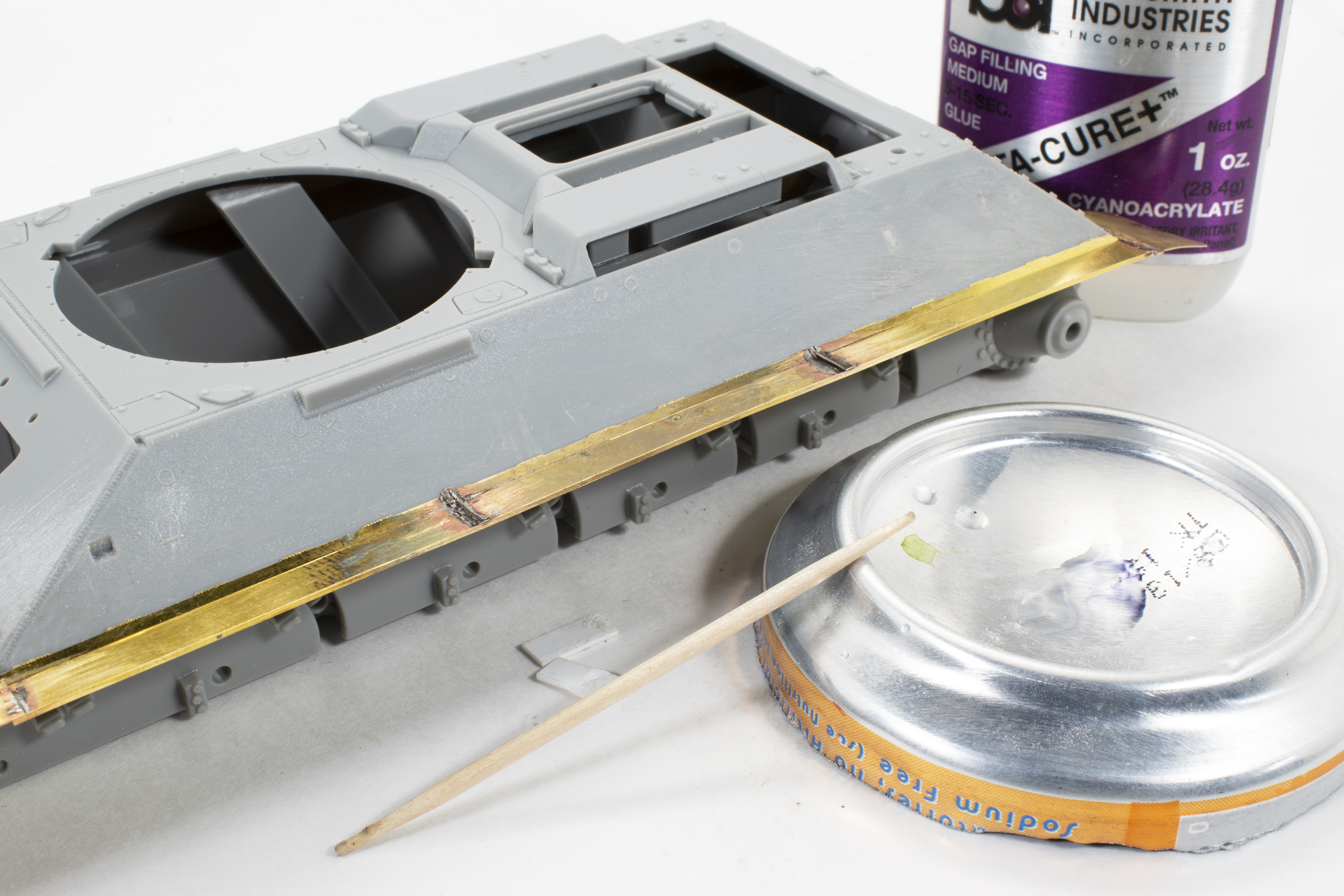
The fenders are glued onto the hull using Medium Cure, Gap Filling CA glue. I like using this type of glue for two reasons; first, the longer drying time (a minute or so) allows me time to move the part and make sure everything is lined up properly before it is set, and second, the thicker quality of the Gap Filling glue helps to ensure a complete bond between parts. As you can see in this photo the glue is set and I have removed the plastic tabs.
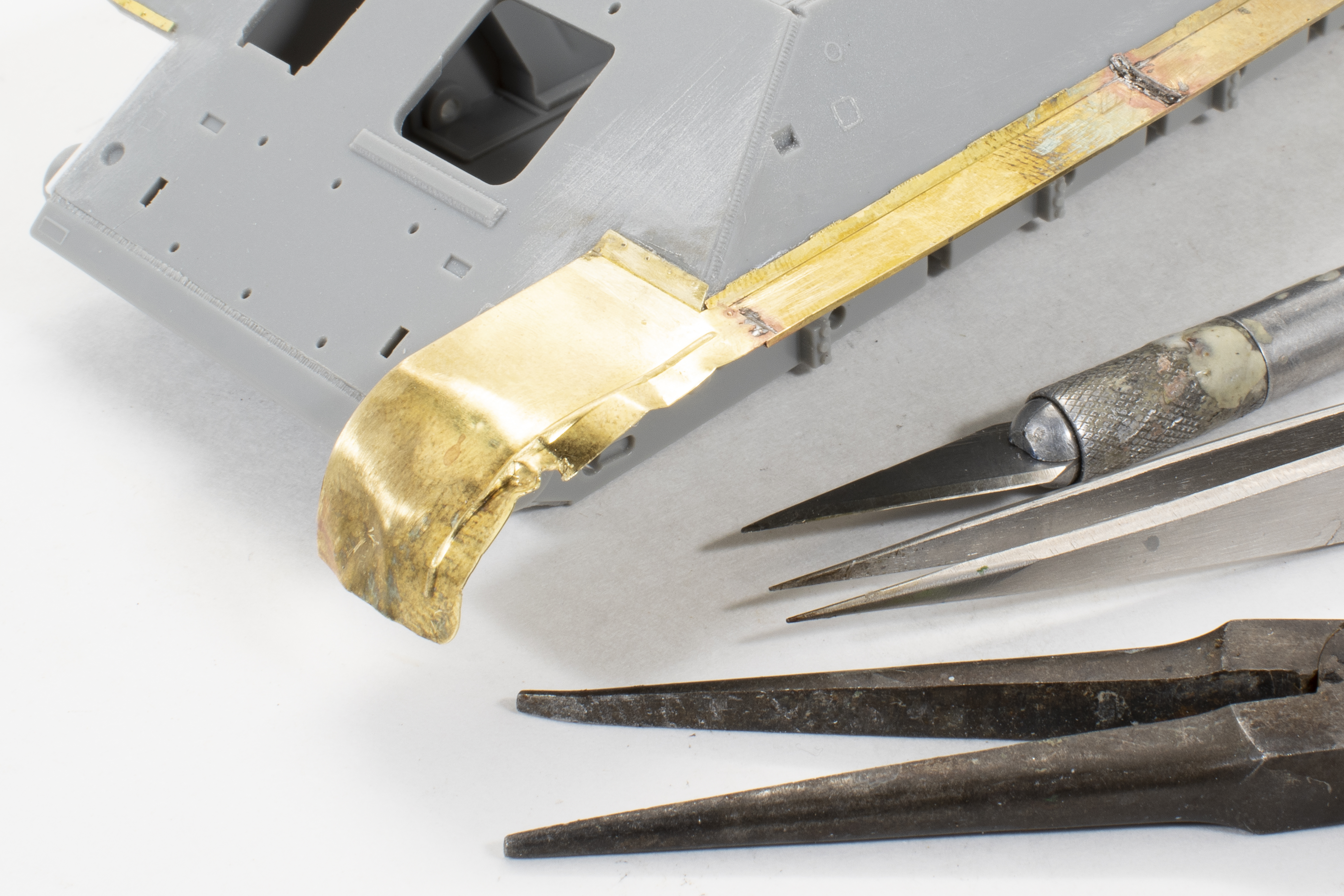 Finally, I get to the point where all of that photo etch and soldering work really pays-off; adding damage. As I mentioned before, nothing looks like bent and damaged metal better than bending real metal (brass in this case). For the front fender, I was actually working to replicate the damage as seen on a reference photo, a crumpled edge with a bit of a tear. An old pair of flat, needle nose pliers, tweezers, and my X-acto are all that is required to create the damage. I continued to add small bends, dings, and damage along the length of each of the fenders. This is where having soldered the support brackets (See above photos) really paid off as I am able to bend and twist sections of the fender without popping-of these tiny parts.
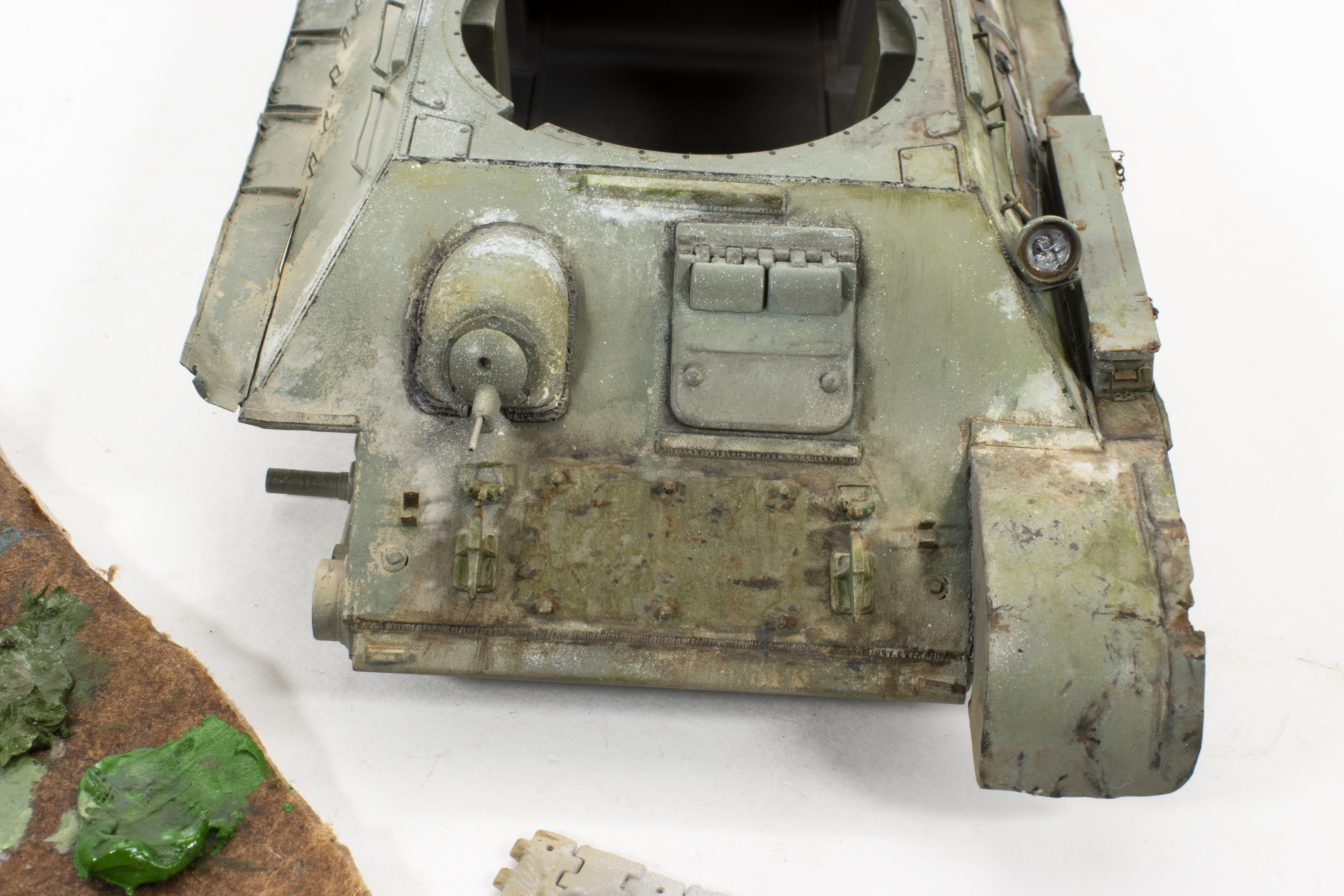
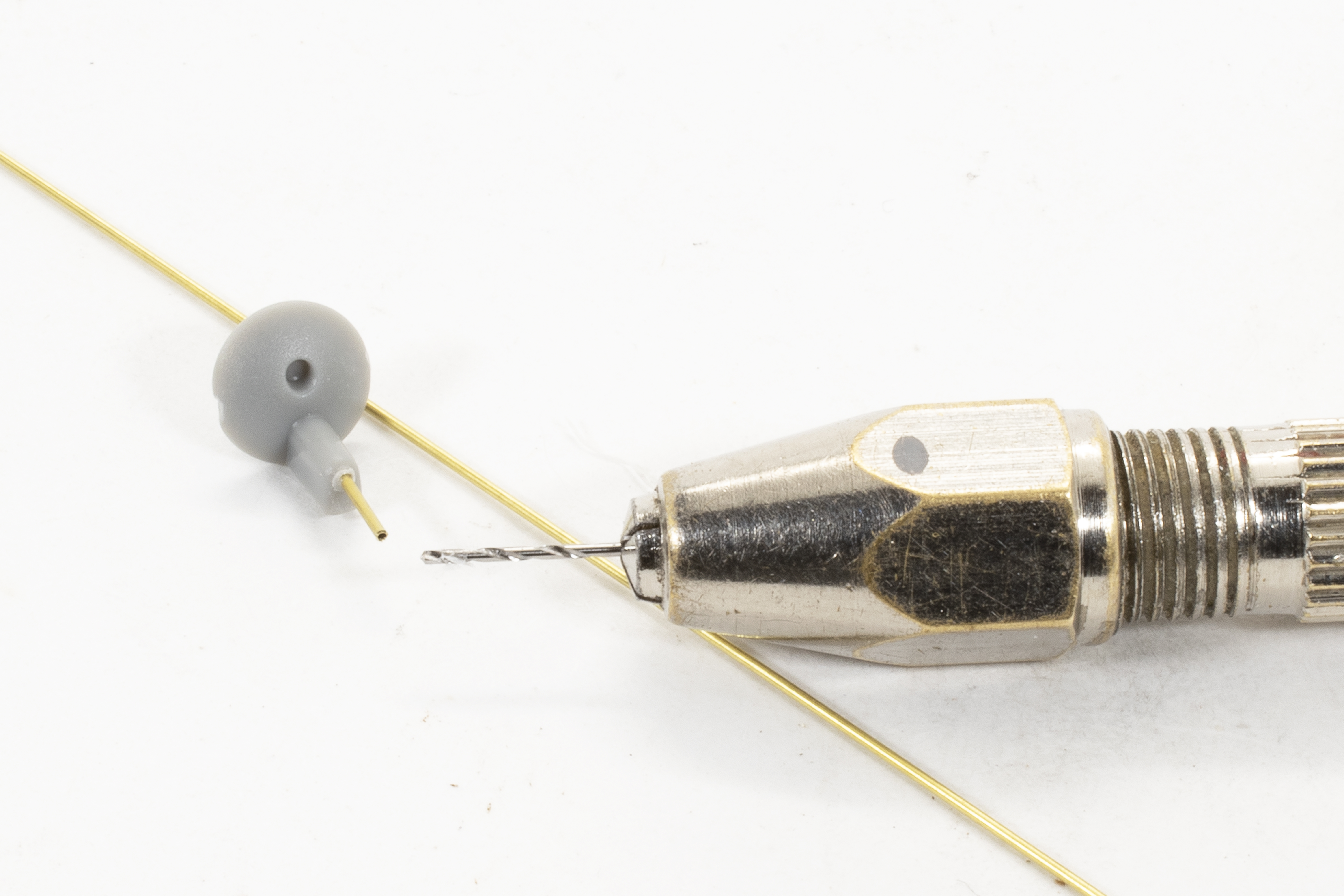 It’s the small details. I replace bow machine gun barrel with a small length of .005mm brass tubing. This was a much easier solution rather than trying to drill out the tiny diameter kit barrel.
The majority of the work, thus far, has been in the removal of kit details and replacing those using the brass etch. I have installed the large engine vent as well as added the intake grilles. The Voyager photo etch kit provides two options for the intake grilles; the first making use of small brackets and brass wire in order to actually fabricate the grille, the second being a single photo-etched part for each opening. While the first option is more accurate as the rods have dimension it is incredibly tedious. I chose the easier, second option and simply installed the pre-fabricated grilles using CA glue. In either case the appearance is far better than the solid plastic kit part.
Ok, these fuel drum brackets are simply a Pain in the Ass! There, I said it. Early on I had decided that this tank would not be carrying external fuel drums – although Voyager does make a nice set. Instead, I wanted to show-off the empty brackets, damaged and bent. This appearance 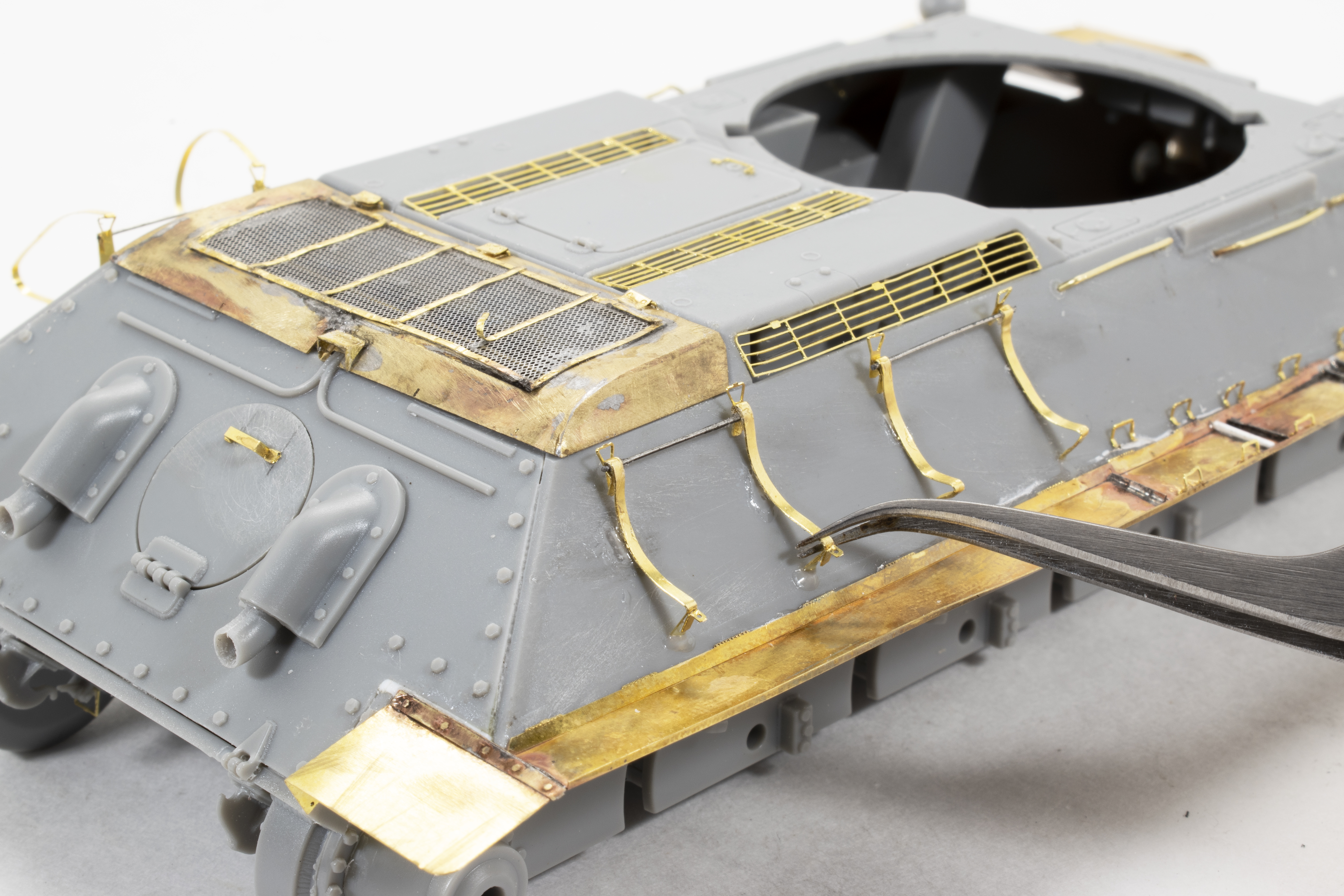 also helped to tell the story of a veteran tank participating in the fast-moving advance with fuel trucks at the ready. These new photo-etched parts are delicate, flimsy little assemblies that wanted to fight me every step of the way. However, I did learn a trick or two, and by the time I built the third bracket, it came much quicker and easier than the first.
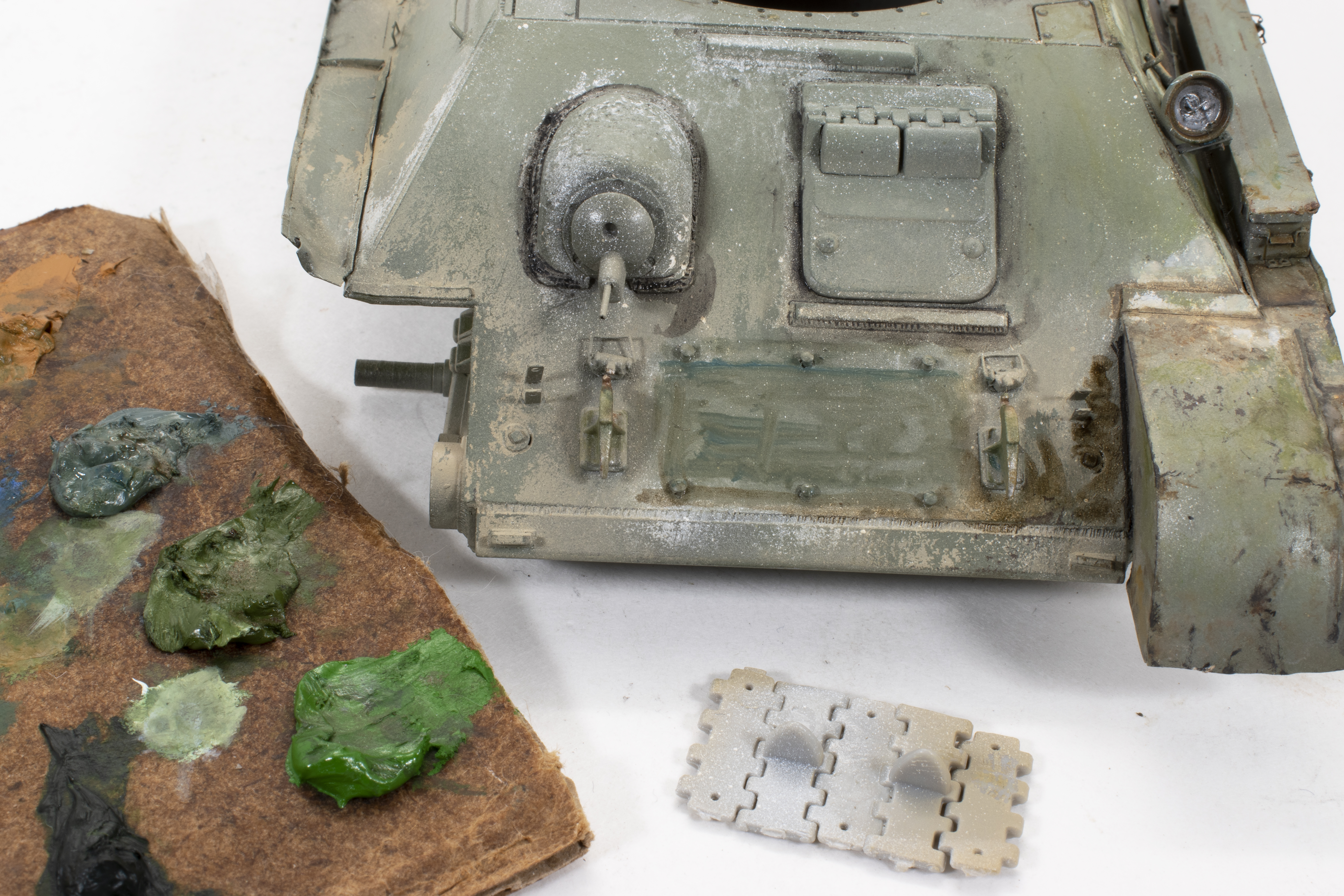
One note to point out – yes, a mistake – you can see that I still have the original small mesh over the rear engine vent and you can clearly see areas that are clogged due to solder and/or glue. At this point, I am already contemplating how to fix this problem – solvents, sanding? As I mentioned earlier, ultimately I chose to replace the entire screen with new mesh.
Honestly, the kit supplied tracks are very nice, single links that glue together quickly and would be very acceptable. However, once I got going on 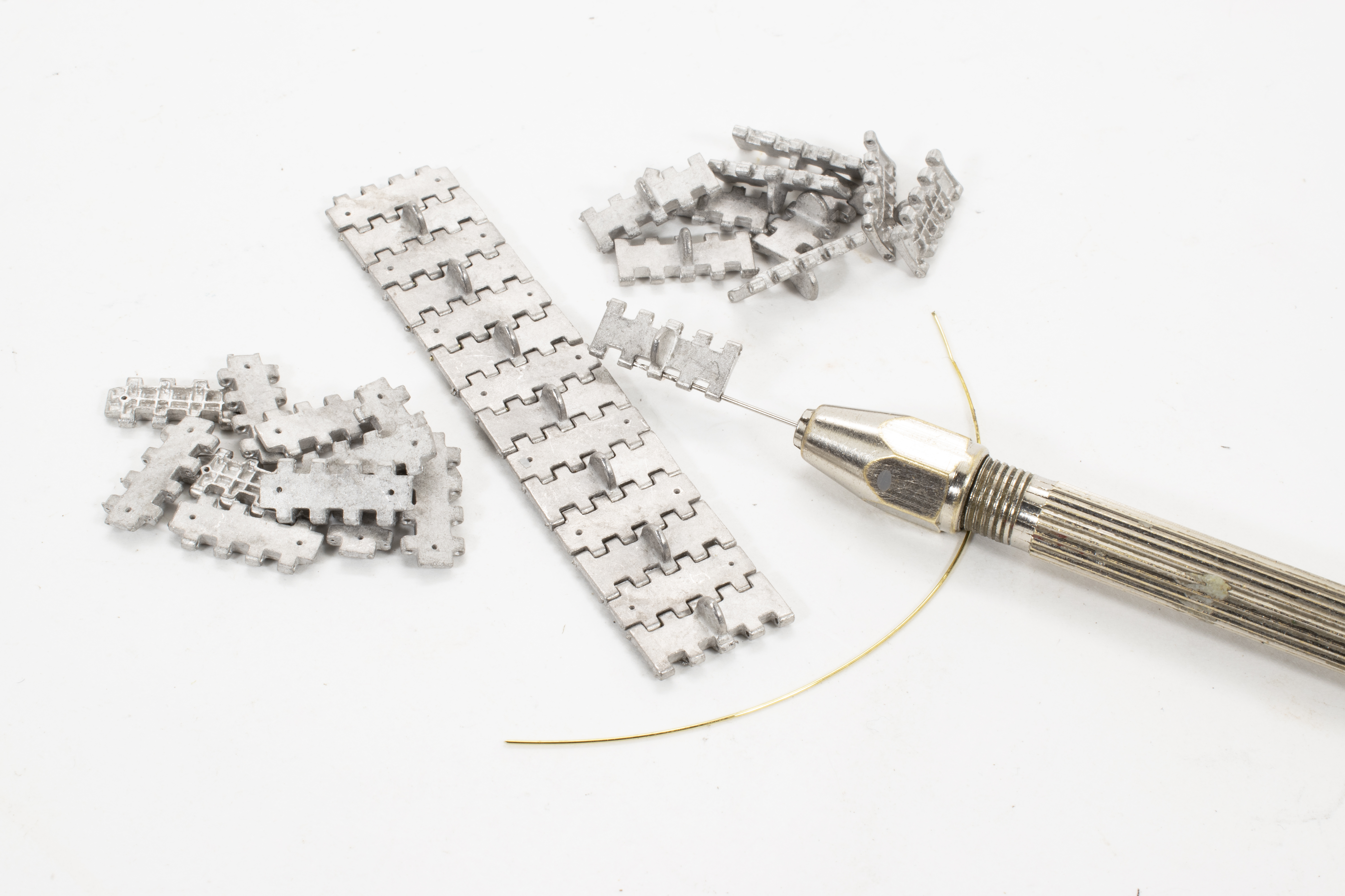 this project with all of the photo-etch I just felt that a nice set of workable metal tracks would help complete the model; give it weight. I have used Fruilmodel tracks on a number of my past projects and have always found them to be of good quality. Just be prepared to spend some quality time drilling out the track-link pinholes, and maybe cleaning up the odd burr or twenty.


I had a few thoughts going into this project on how I might approach the painting and finishing. Primarily, I wanted to break out of my normal routines and try a few different products and ideas. I’ll expand upon this as we move forward.
 The first step in this painting process is the primer. The primer layer is particularly important when building with mixed materials, in this case plastic, brass, and resin. For this step, I chose to use K4 acrylic surface primer overall, and then again in certain areas slightly darkened with a little Tamiya German Grey for a hint of pre-shade. Now for the color, and this is an area where I wanted to stretch out a bit from my usual arsenal of paint products. I had been introduced to the K4 brand of paints over a year ago and have been waiting for the right project to try them on. These are acrylic paint produced in Chile and can be found through the K4 website and online retailers. Thinned only with a few drops of water these paints worked extremely well. I have their range of Russian colors, 4B0, 3B0, etc. In testing, I found that the colors matched very well to references, but for this project, I found that the 4B0, with it’s dark blue/green tones was a great color match but too dark for this project, especially after weathering. Instead, I opted for the 3B color lightened with a few drops of white.


Also notice that this base layer has a lot of variation, light areas, dark areas, and faint streaks. My purpose is to provide subtle variations to add interest upon which to continue with my painting and weathering. Continuing upon the theme of creating an interesting base, a small piece of card-stock is used as a quick masking tool to help define certain features; creating sharp lines and defined areas of light and dark. As long as I have all of the paints out on the table I might as well take care of the road wheels too. I first painted them an overall rubber color using Tamiya German Grey lightened with Buff. Then, using a drawing circle template as a masking tool, the wheels are painted using the same 3B green shades as used on the vehicle.
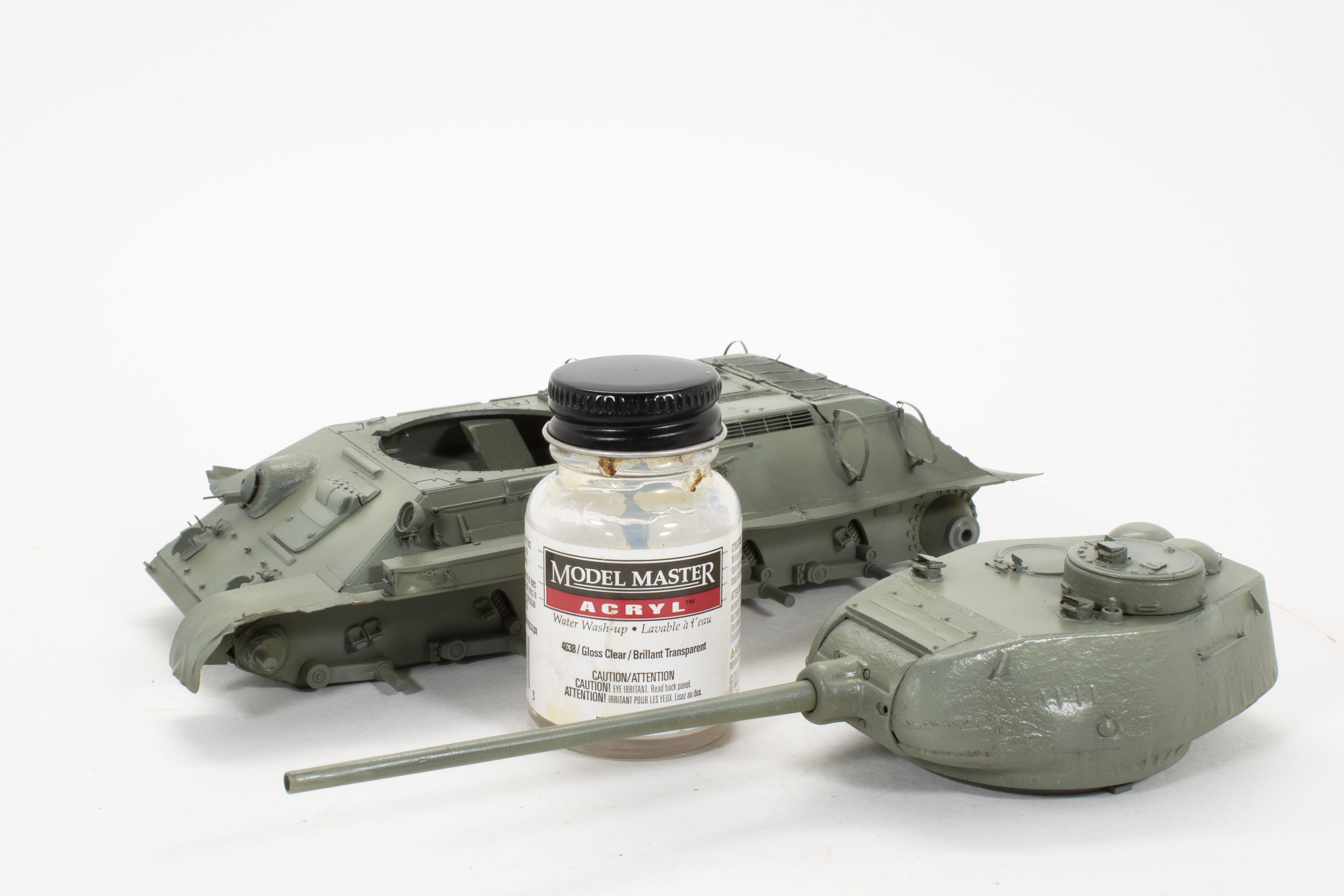 I generally prefer using a protective layer of clear over my base. I do this for a few reasons, the first being that most of the paints that I use are flat finishes, which are great, but I find that the paint is susceptible to staining and other unpleasant or unpredictable effects when working over the top of them. Secondly, I
 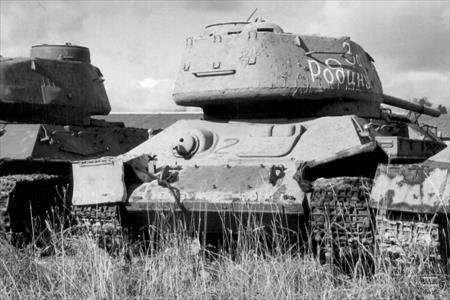 enjoy the ease with which the subsequent layers flow over the gloss surface, this is especially important when applying subtle pin washes.
One additional reason for a protective clear layer is when be applying hairspray or other chipping solutions this layer provides a predictable base for the hair spray to adhere to and allows for more predictable chipping.
As mentioned in my opening, my intention is to portray a veteran vehicle operating in the spring of 1945, with only remnants of winter camouflage remaining. I’m always looking for areas that I can create interest with the model, and so decided to omit the front track link armor. This presents an opportunity to show the “negative”, or the clean areas underneath where the track once might have been when the vehicle’s camouflage was first applied. To begin, I lay the tracks in place using them as a quick mask in preparation for a light misting of white. Next, I applied white patches to the vehicle using Tamiya Flat White over the layer of hairspray. Two points to mention; first, while the white may appear to be applied randomly, I have concentrated the application primarily to areas that would logically be protected from wear. Areas such as tight corners or around prominent surface details like lifting hooks and brackets. Secondly, you can see the effectiveness of using the kit tracks as a kit mask, providing a nice silhouette, or template, for further weathering.


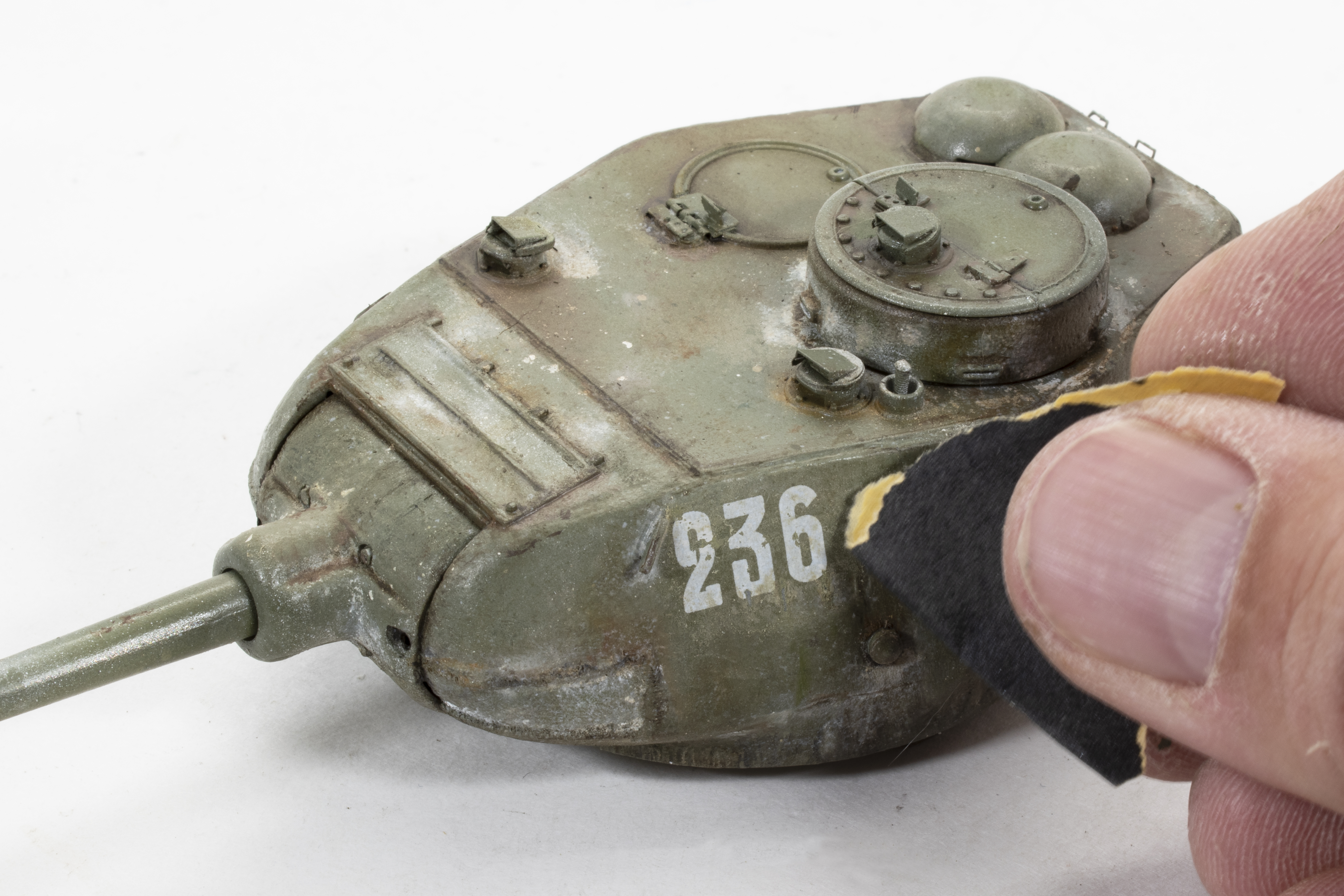
The oh-so-familiar scrubbing when employing hair spray or chipping fluids. Since my goal is to only have remnants of whitewash, accuracy isn’t my primary concern and so this larger sized brush is ideal and quickens the pace.
As I mentioned in my opening I hoped to push the limits of using artists’ oils on this project, at least a little further than I do traditionally. In the past, I would add oils to influence the tone of the base, initiate paint fading, and to perhaps lay a foundation color for a final finishing using enamel effects and/or pigments. Usually, I will get to a point where I feel I have achieved all I can from the oils, then move on to other mediums. On this project, I’ll try to resist that temptation to move on and keep with the oils.
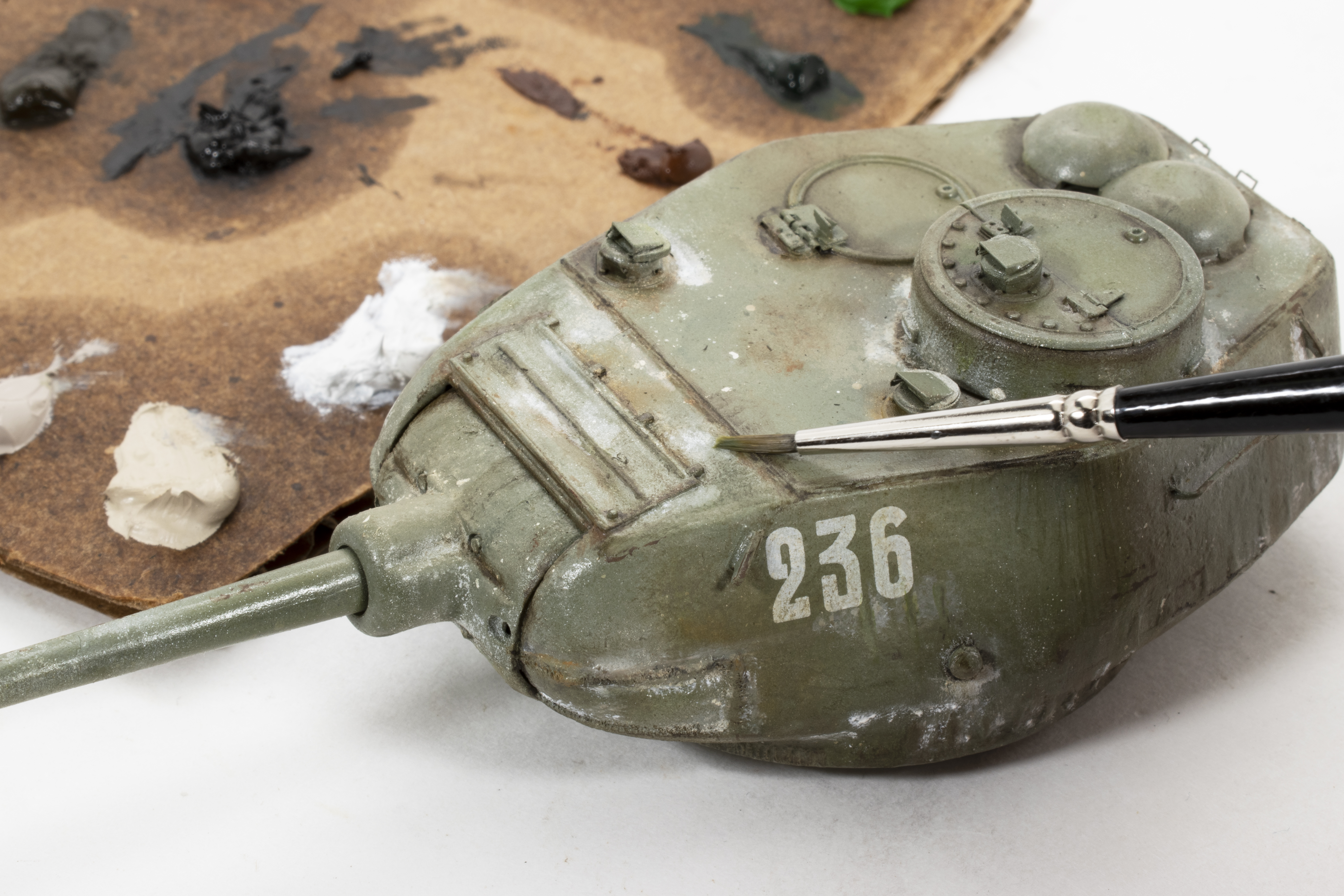 I begin by setting the color tones on the turret. This choice of colors is important and consistency needs to be maintained throughout the weathering process. As you might see from the palette in the background I will be using the oils to adjust, or enhance, the dirt tones, the base colors as well as the whitewashed area’s.
One final step of preparation before I begin weathering, a light sanding using fine grid sandpaper over the turret decals to add a bit of wear and take off some of their sheen.
 Over time my thoughts about applying chips have changed quite a bit. In the past, chipping was a separate, but integral step in my finishing process. Not only was it fun to do, but the chip also served to help outline and define features on the model. You know the drill; chip (maybe of light and dark colors) around the hatches, chip along the edges, chips on the fenders, and chips running down the top of the barrel. At some level, I began to feel that chips applied in this manner were becoming a weathering crutch and that my finishes were becoming routine and predictable. I began to wonder if chipping, at least in this traditional sense, was even necessary. Furthermore, when studying reference photos I began to understand that this entire pattern was at best unrealistic, and at worse an exaggerated caricature.
As my use and control of oils and enamels has expanded, I have almost totally eliminated adding chips as a separate step for the reasons described above. However, that doesn’t mean that chips don’t exist and that wear isn’t a part of an AFV’s experience. And so the challenge is how to express this wear in a more realistic, even restrained method. In most cases, subtle chips, blemishes, and texture are all-natural by-products of using oils and enamels without needing to overthink or control the results.
 On localized areas where more extreme wear is present, simply tapping the edge of a brush lightly loaded with artist’s oils can easily create a pleasing and realistic chip, or in this case a rusted surface.
The front hull, the “blank canvas” as I begin working with the oils. Obviously, when looking at this photo you can observe that this is anything but a “blank” canvas. The earlier preparation of the surfaces by adding color variation to base green and through the use hairspray provides a lot of interest to the whitewash and buff layers and has certainly paid-off with many creative opportunities. I begin working in this area by adding subtle shading using a dark brown color around the driver’s hatch. I will repeat this technique around other prominent surface features and along the edges of the hull. The exaggerated size of the brushstroke, as seen here, will later be blended and softened as work continues.
 Most dramatic is the preparation of the area of the missing spare track armor. My thought here is that the tracks provided some amount of protection from the elements, and as such helped to protect the paint from fading., However, being that the area is under the track accumulations of dirt and abrasion marks would be present. Again, I am using oils to outline and define the area and add slightly different tones than from the other areas of the front hull. It all looks a bit random now, but that is part of the charm of using oils. I will work to tighten it up as I go along.
Moving right along with my work on the front hull. Changes of note from the prior photo are that I have to a large extent worked with the green base color over the entire hull, and as can be seen, the oils have produced depth and subtle color shirts. The right fender has also received some extra attention and is beginning to look properly dinged-up. Keep in mind that all of the wrinkles, dents, and scratches have been produced only with oils. As for the missing track area, it’s obvious that this is still a work in progress, but I can see that I’m heading in the right direction, even if only that this chaos looks different from the surroundings. The nice thing about working with oils is that I have plenty of time to come back and refine areas. Matter of fact, simply leaving oils to sit and rest for a few hours often changes their appearance, some areas blend, while others may fade during drying. I’ll continue to work in this area.
This side-by-side photo helps to illustrate the power of using oils. 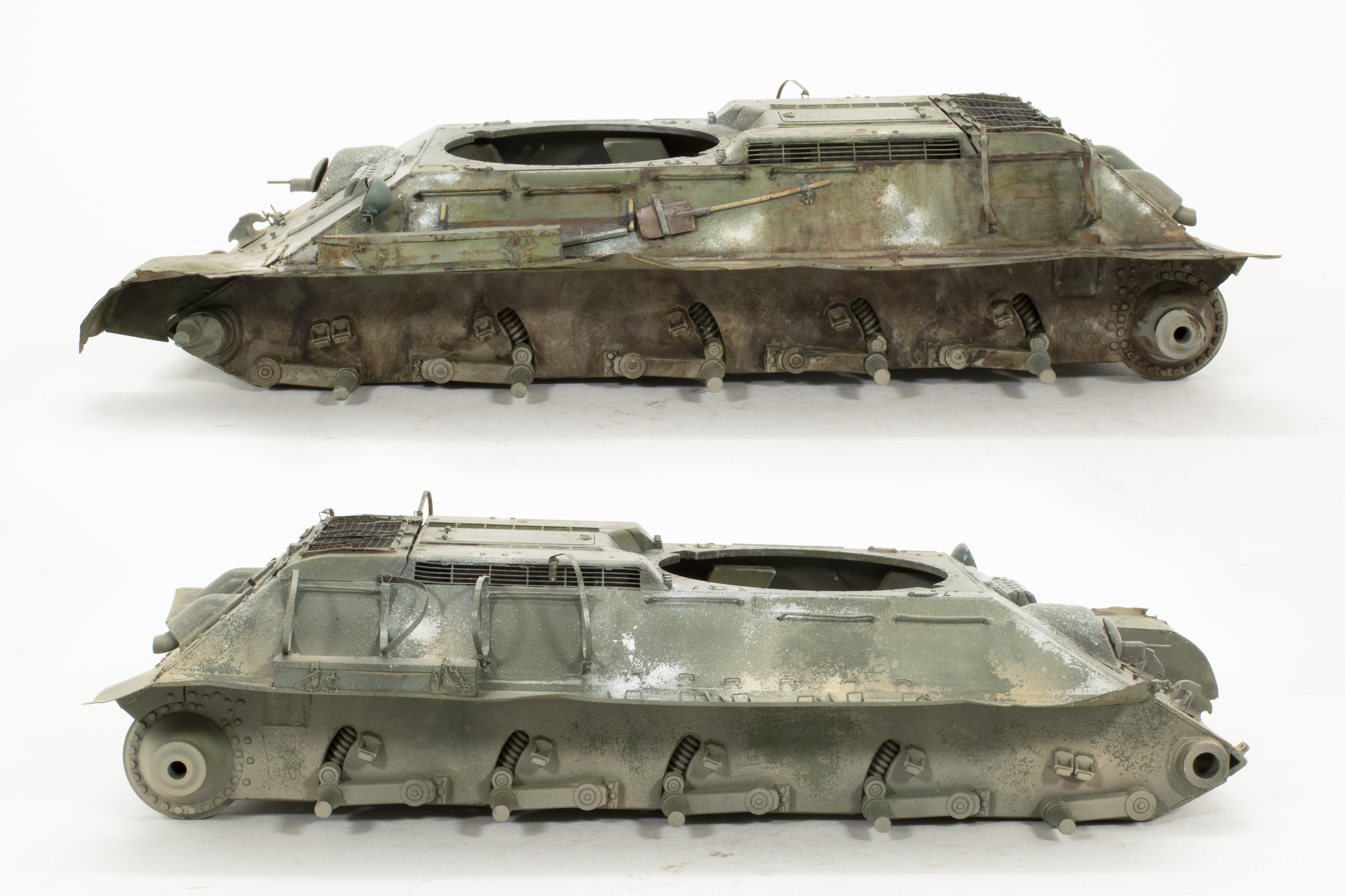 The top photo shows the left side after my first round using only oils. The bottom photo shows the base before oils, the starting point after the base color, and hairspray treatments. As I work, I often take photos such as this to review my progress and help me see areas that might still need attention. And yes, I see a lot of areas that I
 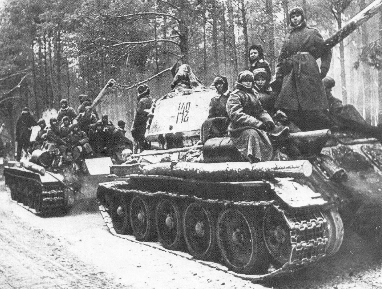 will be intending to. My intention for this project was to stretch my use of oils and limit my use of pigments and other enamel weathering effects. This photo clearly shows the power of using oils.
The Fruilmodel white metal tracks are treated with a burnishing fluid (Blacken It) that I purchased from my local train hobby store. The guide teeth and other contact areas are polished in order to restore the original metal color of the tracks. These same areas were further enhanced, or polished, using the same Dark Steel pigment color as used on the road wheels. The reverse side of the tracks is treated with a combination of earth-toned pigments. These colors were mixed together in a side dish and then stippled into the crevices of the tracks followed by a light application of pigment fixer to keep them in place. As a final step, the raised surfaces were lightly sanded for a polished sheen on the contact points.


![]()