
Pulling Power -Holt 75 Tractor
 I recently took a bit of a break from my usual modeling subjects, those being armor, armored cars and other types of earthly vehicles and instead dabbled in the world of those winged things, specifically a couple of WW1 aircraft. It was a nice and needed change of pace. One of the takeaways from that experience was the process of working on the many subassemblies, each as a separate little jewel of a model – from construction through painting and even weathering – and then moving onto the next element until finally it’s brought all together.
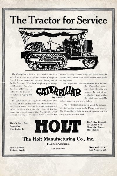
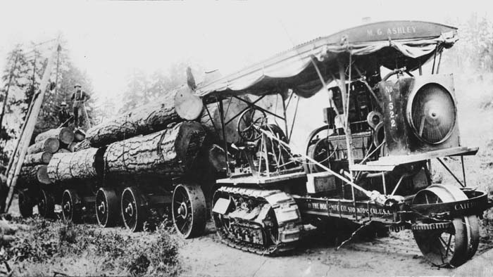
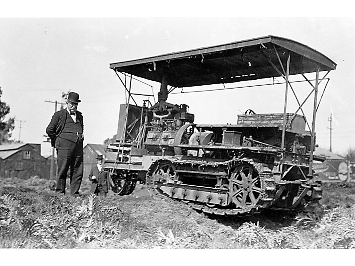
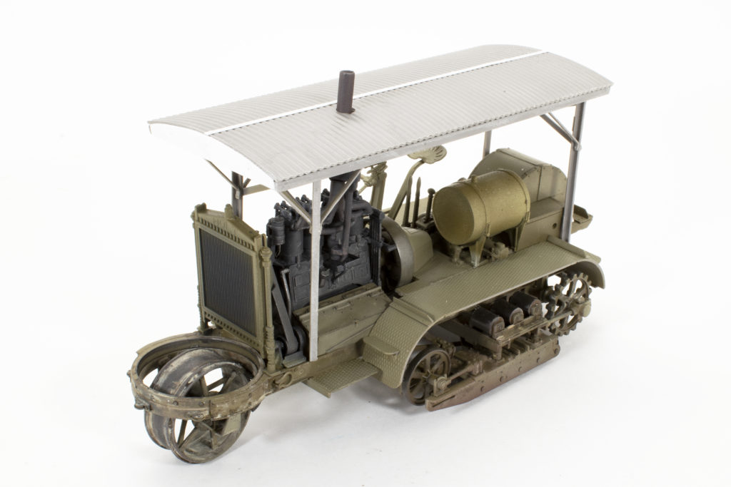
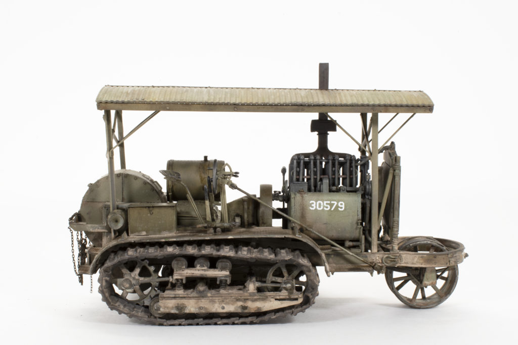
This now brings me to this current project, Roden’s release of the Holt 75 tractor. As with so many early 20th-century war machines, the Holt 75 began it’s career in civilian service as an agricultural tractor but came into its’ own while being utilized during the construction of the Los Angeles aqueduct system beginning in 1909. With the outbreak of WW1 there was a need for heavy prime movers to haul around the Queens of the Battlefield, the heavy artillery pieces. Durable, able to maneuver over uneven terrain and readily available, the British War Department placed orders for the tractor, of which some 2000 saw service with the British, French and American forces 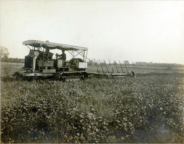 during the course of the war.
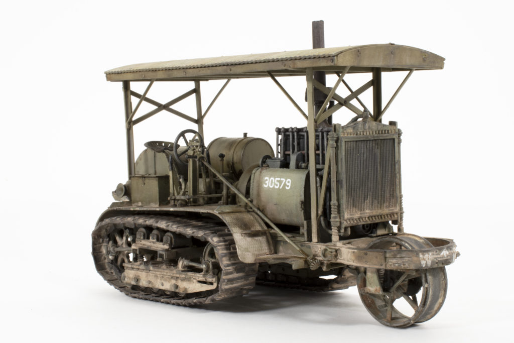
What better way to continue my WW1 initiative than to delve into this utilitarian, albeit ungainly looking beast. Fresh off my recent aircraft endeavors I decided upon the outset that I would try and build this project in stages; finding component groups or subassemblies, and constructing and painting as I went along. You will see this approach unfold throughout the process. In all candor what I had hoped was that this new release from Roden would not have many of the difficulties of construction as has plagued some of their earlier releases, but unfortunately, that was not to be the case. The reality was that I ended up doing quite a bit of sanding and re-detailing of parts in order to make it all look presentable…of course, there was much more that could have been done for those of you looking for a competition-worthy project. In the end I the kit built into a nice representation of the tractor…now, wouldn’t it be nice to have a few Allied artillery pieces to go along with it!!
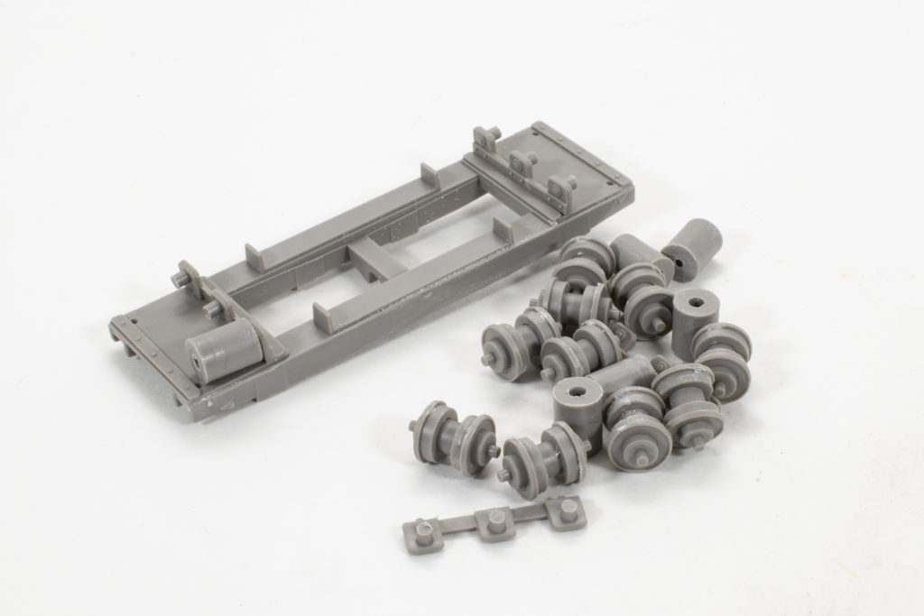
Construction of the model begins with the running gear, specifically the top rollers and brackets. The parts at this stage displayed somewhat heavier seam lines than most newer release kits, but nothing that a bit of sanding wasn’t able to fix. The left and right sides of the return rollers and their assemblies begin to come together. As you can see I am following my “paint as I go” plan, which especially at this stage works great as I’m easily able to paint the rollers separately from the brackets. The rollers were painted using AMMO Steel with a light wash of Ammo Rust Effects highly diluted and then almost all removed for only a hint of color.The component parts laid out for the front wheel/roller. It’s at about this point in the construction that I’m beginning to question the clarity of the instructions and fit of the parts. But, as they say – bugger on.
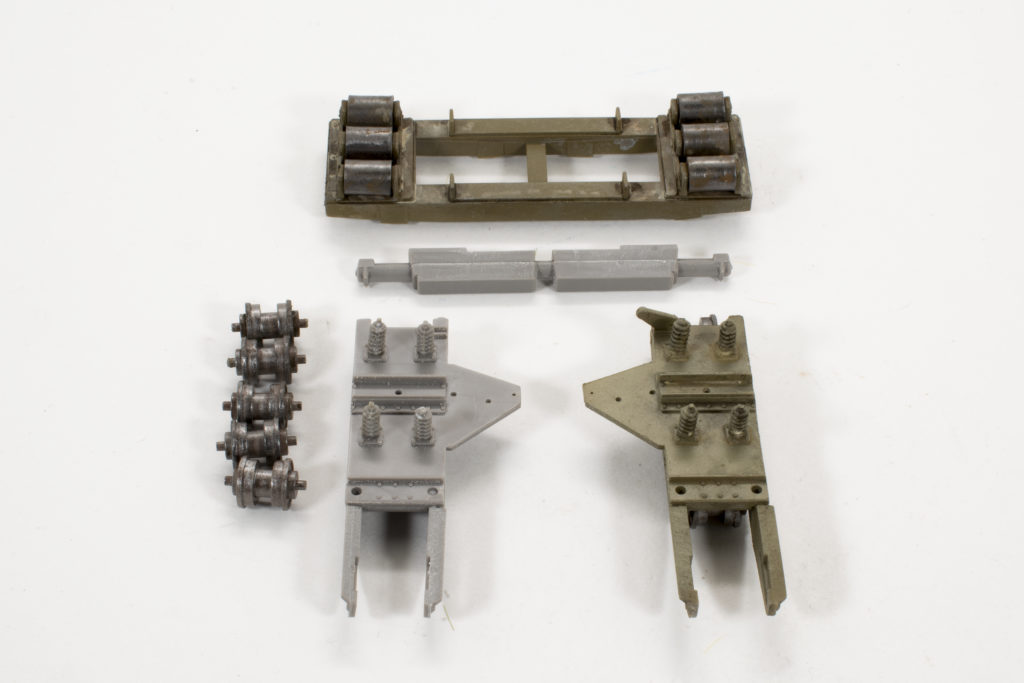
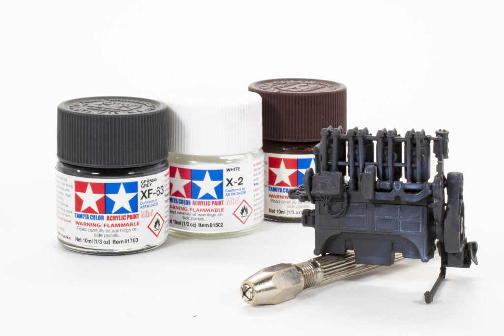
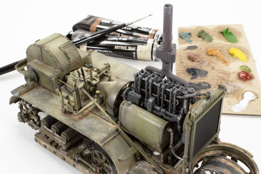
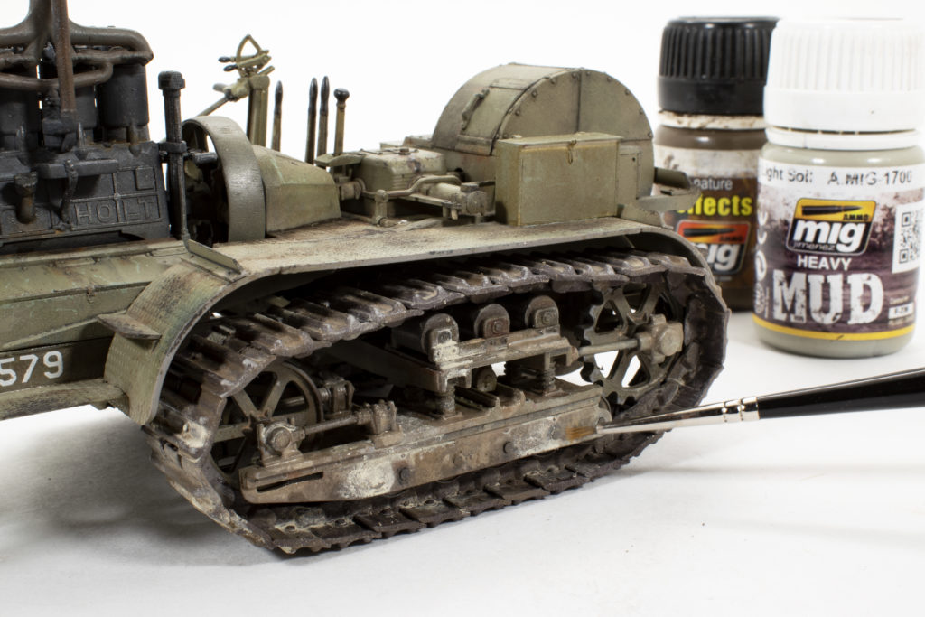
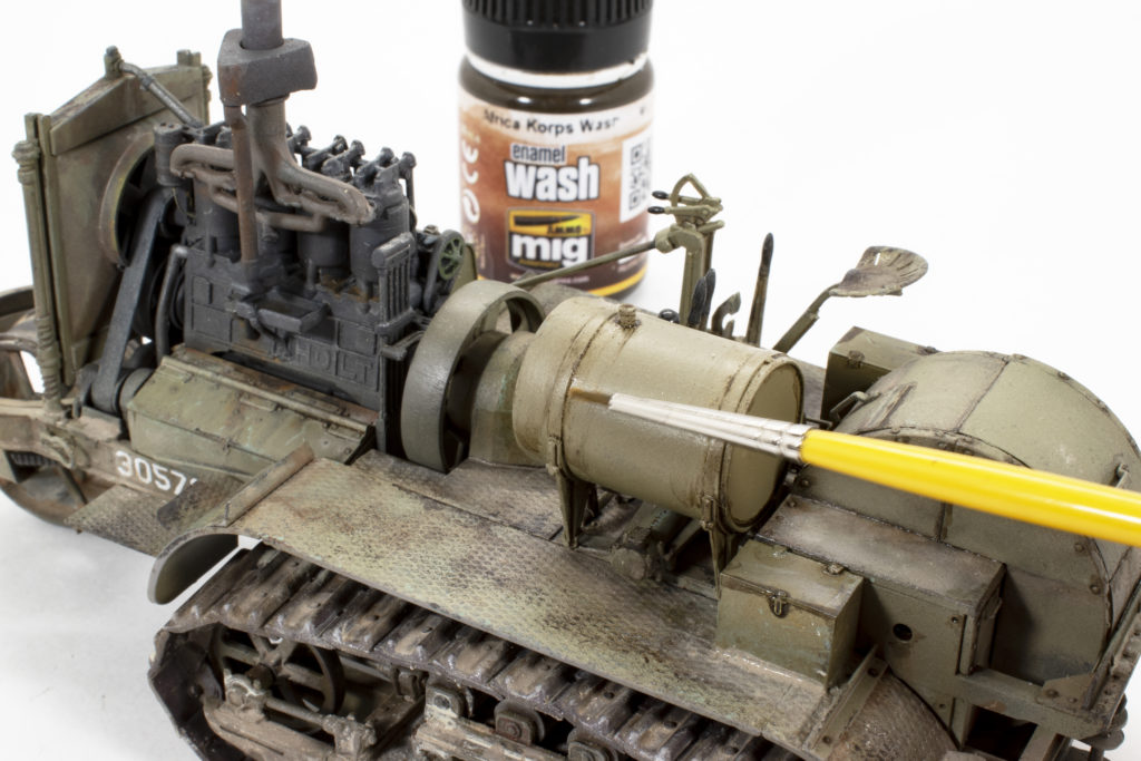
These are the color players that I’ll mostly be using throughout the project. The base color is Ammo Green Moss lightened with Vallejo Off-white and thinned with tap water. Weathering consists of creating a base “roadmap” if you will using Ammo Africa Korps Wash, Earth Effects and Light Soil Mud Effect, mixed in various ratio and diluted. Generally, I use very diluted mixes when applying enamel effects and washes. Working in subassemblies, I have the front wheel fully assembled, painted and a good way toward final weathering. Although early along in the process, this sub-assembly piece set the example for all of the weathering colors and effects that would follow on the vehicle as a whole. 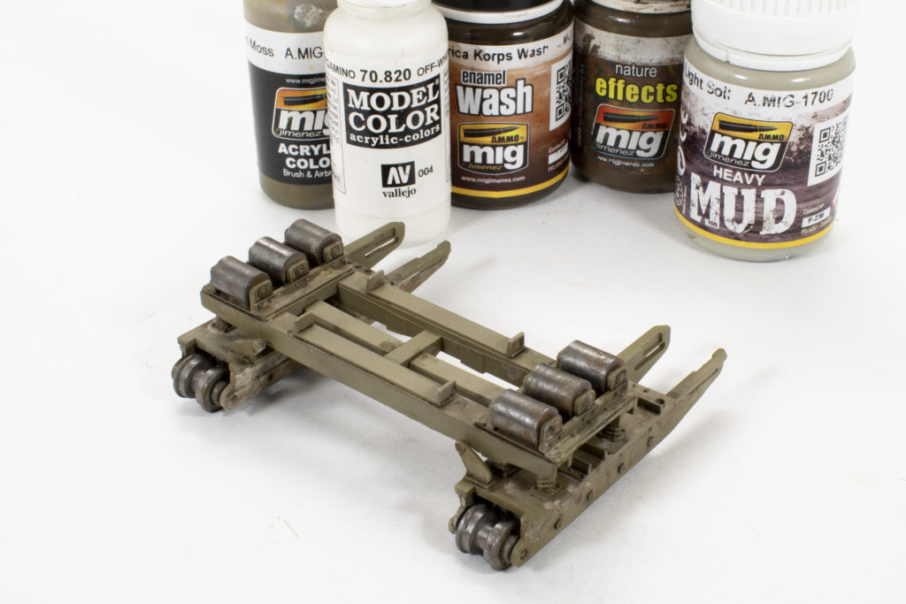
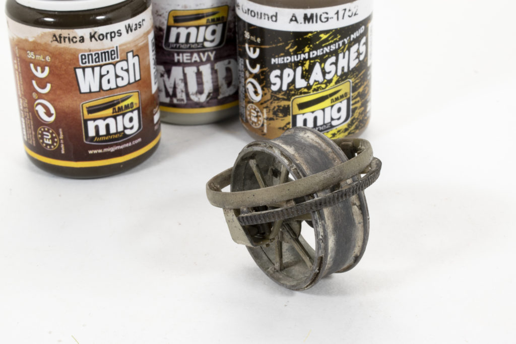
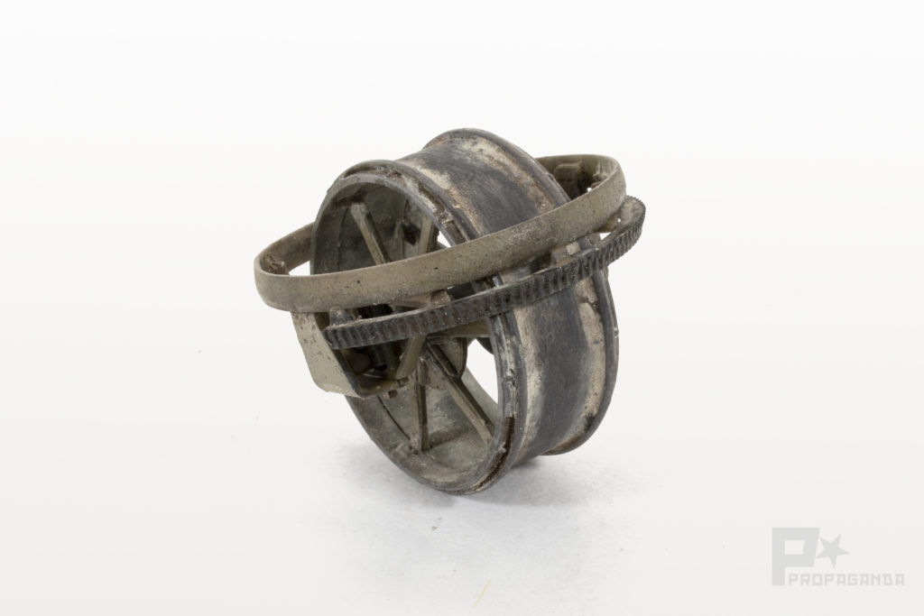
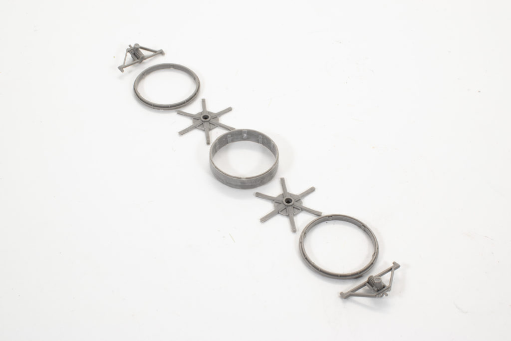
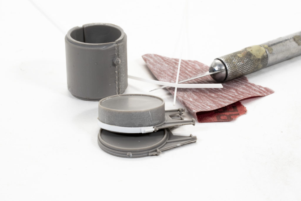
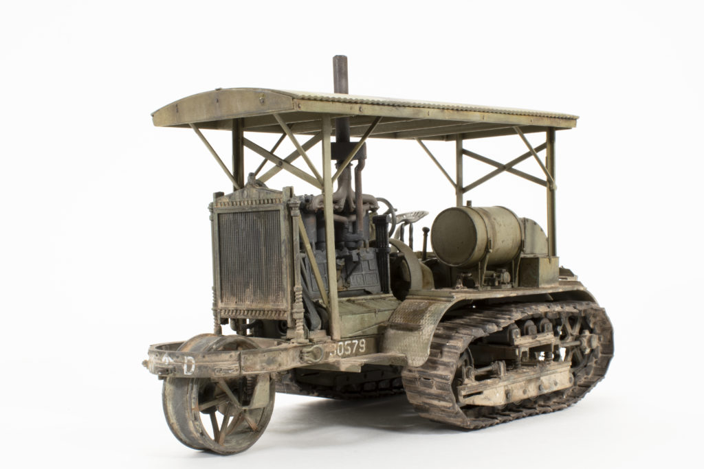
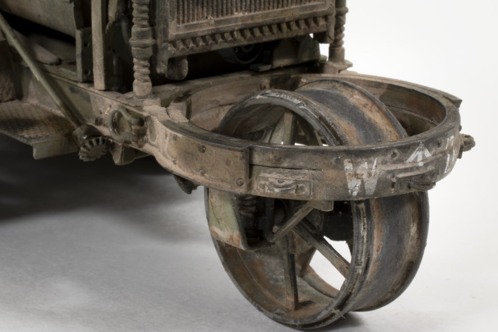
It’s at about this moment that I am coming to realize that this new mold, new release kit isn’t quite up to standard and that a bit of effort modeling effort will be required. The prominent ring at the front of the tractor, yes the focal point, was horribly miscast. It is a multi-piece assembly that had very large offsetting seam lines; so much so that the pieces didn’t even appear round in shape. My solution to all of this was to scrape and sand off all of the surface details, and the rings until they were back to shape and then add back on the surface details. I installed the front wheel ring assembly onto the chassis and then painted it my mix of Moss Green lightened with White. Initial details are pointed out using a pin-wash of Africa Korps wash.
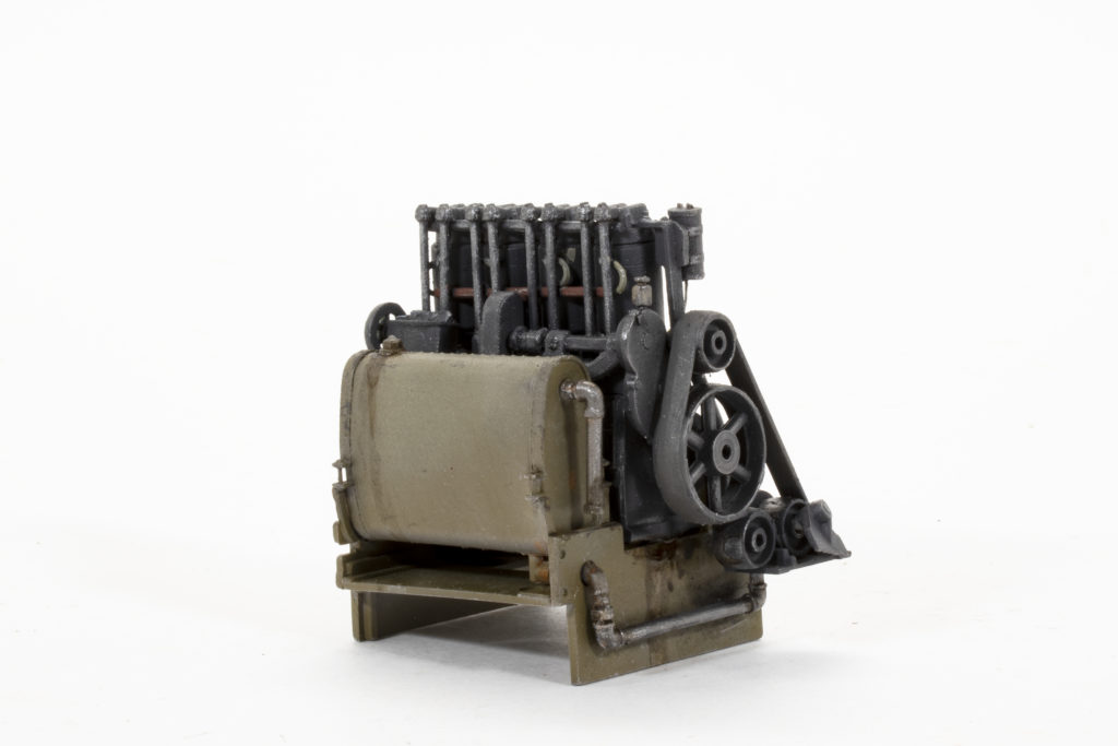
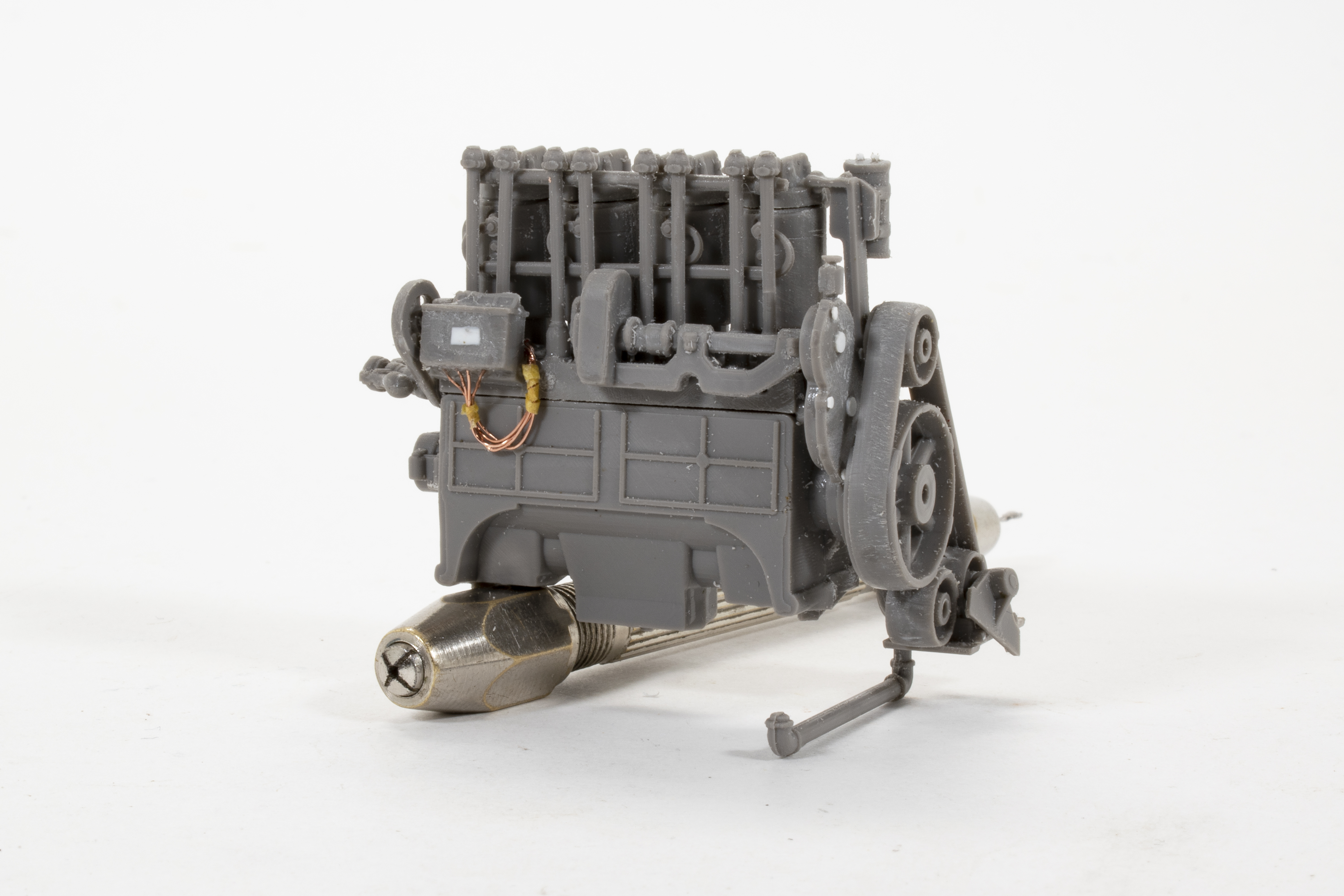 The next steps brought me to constructing the engine. Once again these parts suffered from the same issues of large, offset seam lines and soft. And, once again I took to sanding many of the parts back down to their basic shapes and then re-applied the surface details. While I was at it I went ahead and added a bit of the wiring just to busy it up a bit, but in the end, most of this work would be hidden.
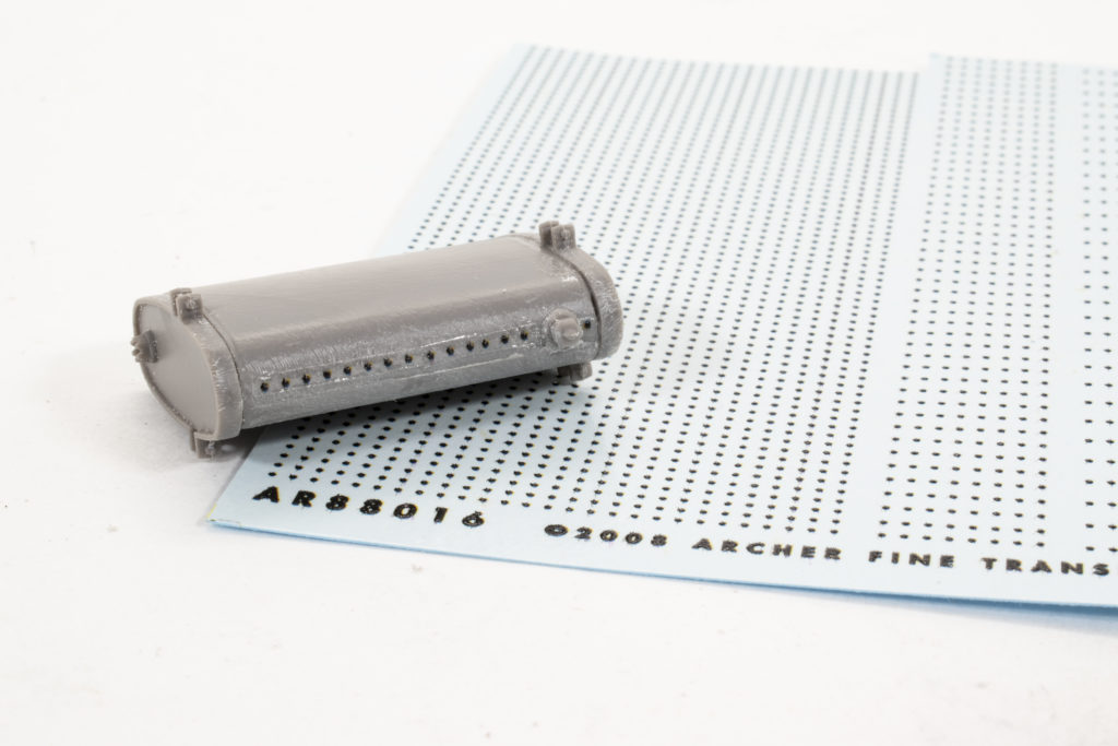
You can see here a clear illustration of what I mean when I say that the seam lines are large, and offset. This is the large flywheel that sits to the rear of the engine. The sanding stick is my friend! The water reservoir that sits along the right side of the motor suffered from the same issues of fit and seams, and as such the smaller details such as the rivets had to be sanded away (they weren’t that nice anyway). These were re-applied using Archer Fine Transfers raised heads. The engine was base painted using Tamiya German Grey tinted with a bit of White and Hull Red. 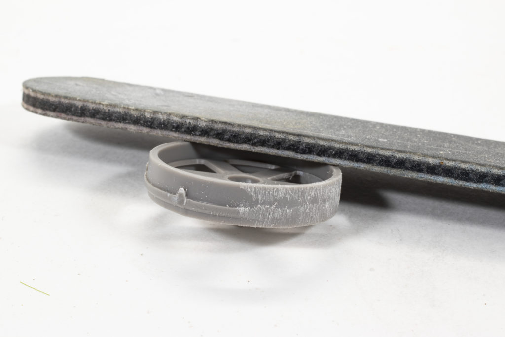
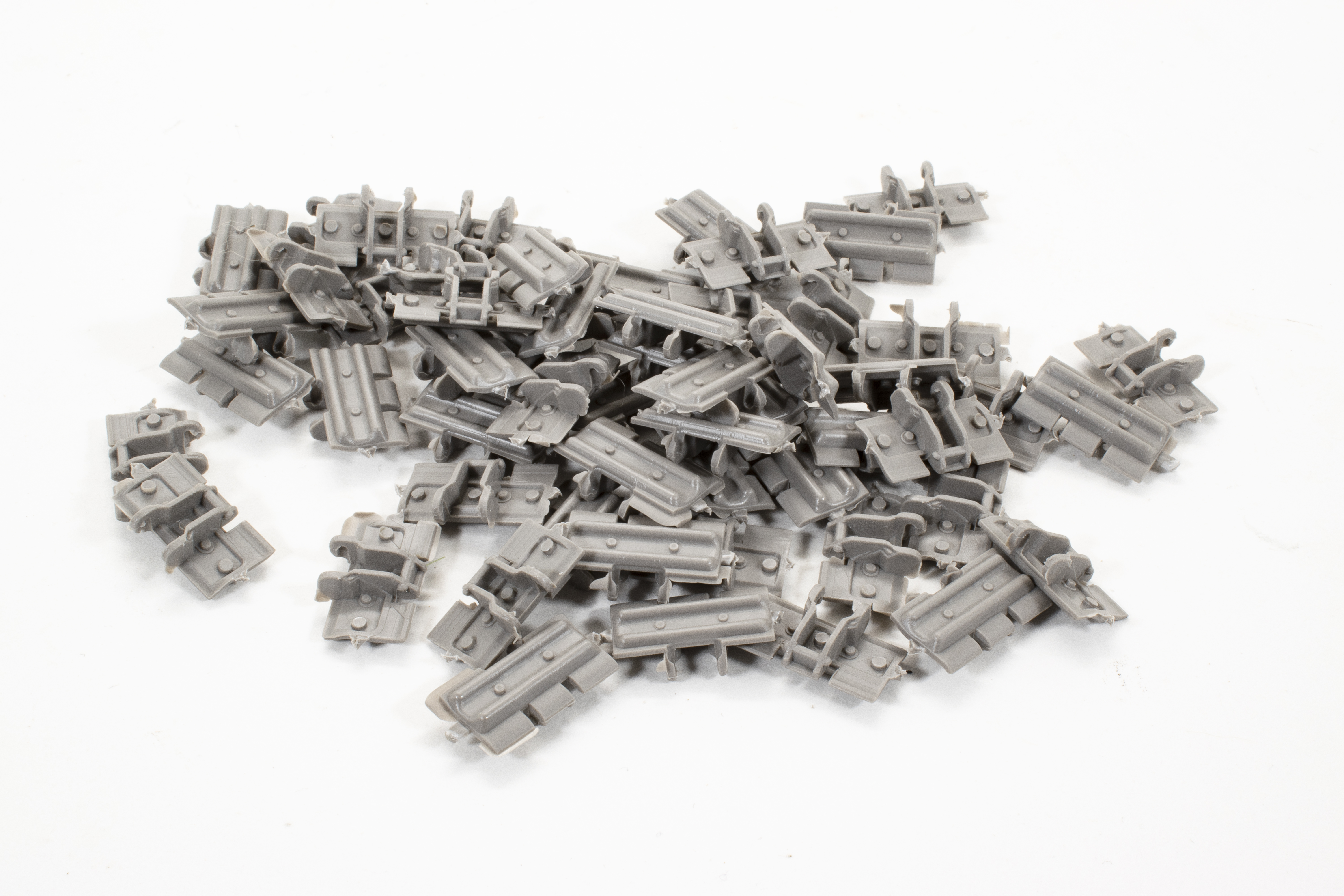 Ok, speaking of frustrating, I’m going to say it right now; the guy who is responsible for the molding of these tracks should find another line of work. To say that they needed some cleanup is, to put it mildly. Each link has 3 large injection pins, one being in the center of the linkage. The “snap together” connection surfaces are rife with flash, warp and nasty buggers that required a lot of filing and sanding just to get them to sort-of fit. Ok, I’m over it….let’s continue.
 Now here is an interesting engineering idea. The fenders come to you on the sprue as shown with the top fender in this photo, that is flat with an upward curved section to either end. In order to get the fenders to the proper shape, you are asked to bend the end sections downward as shown on the bottom fender in this photo. There is a scored line that aids in the process, but geez! talk about all sorts of things that can go wrong least of which is simply snapping off the parts. Once in the “proper” position, you are still facing a small gap in the top tread pattern where the bend is made (something that I didn’t even try to fix), and some very iffy connection and alignment issues as you install them onto the chassis
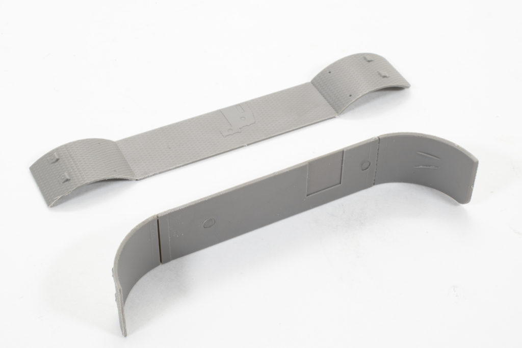
And here we go again, this time the reserve fuel tank. Given that poor fit between the halves and poor feature, it seemed much easier to sand it all down and replace the details. These little fixes are not that difficult to do, and honestly somewhat satisfying and certainly help in the final presentation.
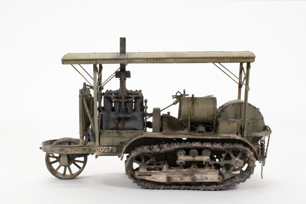
 One last major hurdle…here we go. This roof has problems all over the place, but we’ll only talk about the most obvious and that being the line of sink-holes that run down the middle of the arch. At this point, I actually pondered the idea of scratch building the entire structure, complete with new corrugated roofing – which by the way would have at least been close to scale thickness, but I digress. In the end, I chose the easy way out, I simply laid a strip of Evergreen along over the divots, added a few bolt heads and pretended that is was supposed to be like this all along. A quick test fit of the roof onto the tractor and things look just fine. All is forgiven.
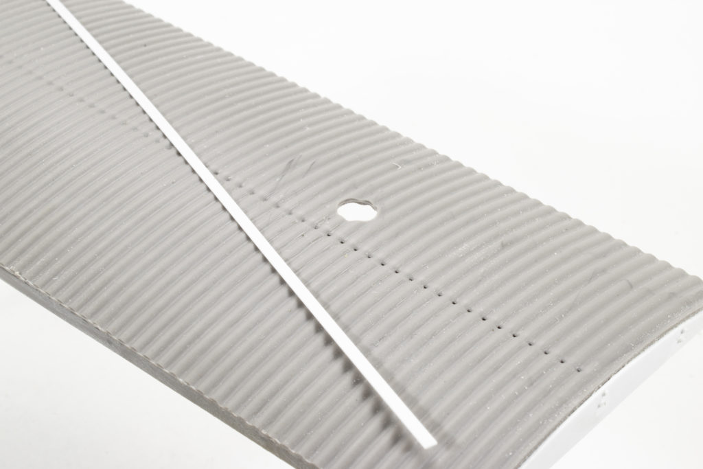
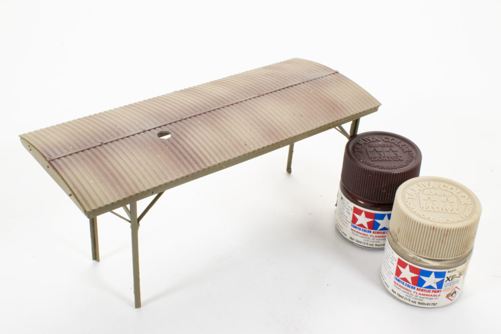
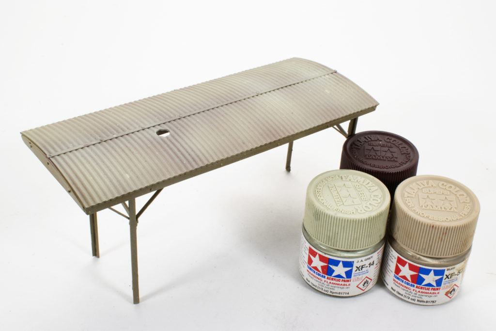
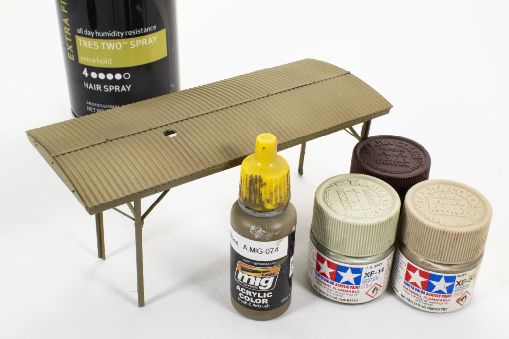
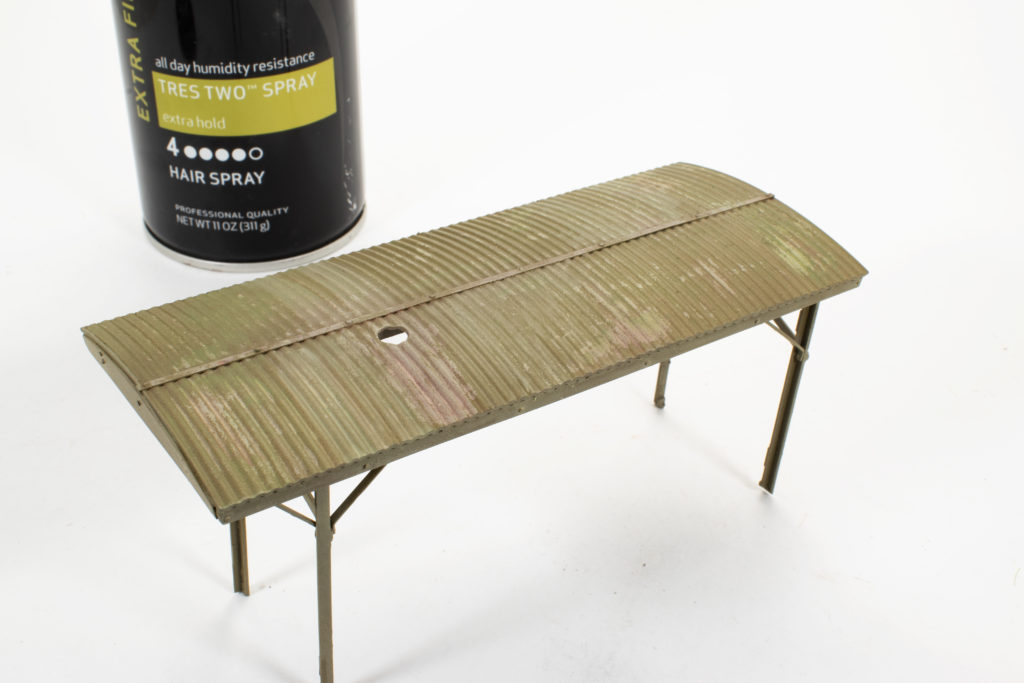
Speaking of the rooftop, let’s paint it. My thought on this was that it was correlated metal and back in the day it was probably more raw steel than galvanized and so rust would be an element. I begin by painting am undercoating of Tamiya Hull Red in a rough pattern of how rust and run-off might develop. Next, I applied an overspray of Tamiya Buff that serves to tone down the rust color and also provide a base color and then applied a light misting of Tamiya Sky to further unify and promote a faded, oxidized appearance. 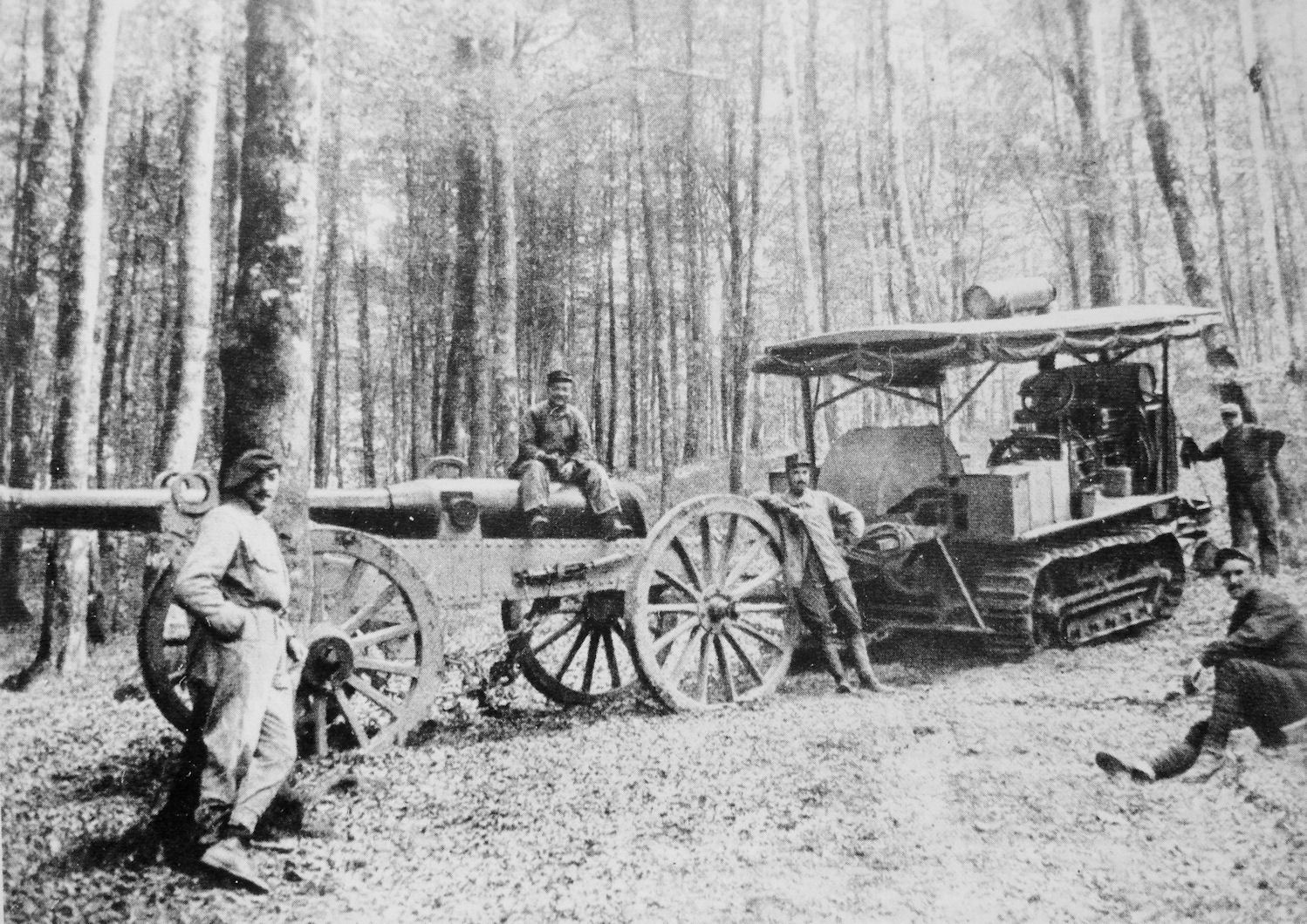 Once these base colors had dried I gave the top surfaces a light to medium layer of hairspray. I let the hairspray set for about 15 minutes and then gave the entire top a final, light overspray of the Ammo Moss Green color that I have been using throughout the build. Again, I let the paints set about 15 minutes and then I began to scrub the surfaces using an old brush moistened with water in order to reveal the colors underneath. In this case, I tried to be careful and only reveal the rusty, oxidized colors in areas that would show wear such as near the exhaust. Light applications of oils followed as well as pigments to enhance the effects in which will be shown in the final photos
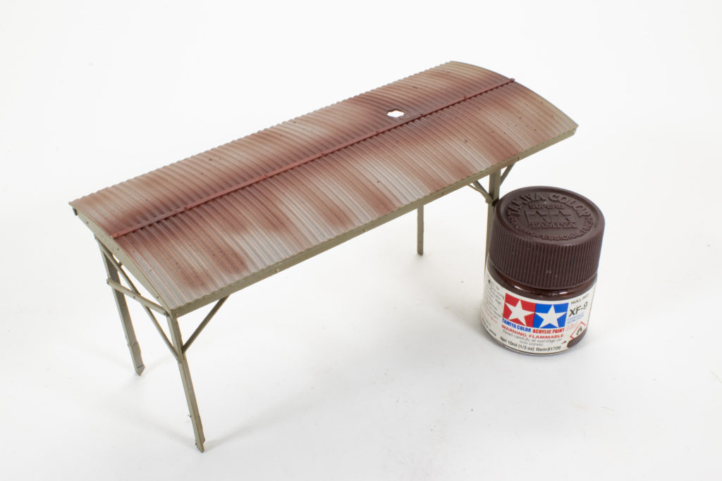
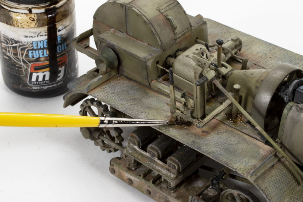
As I mentioned in the opening I had decided to do all of the painting and some of the weathering as I built, so now, with construction complete, it’s time to finish with the weathering. A sponge is used to lay down areas of high wear on the fenders and steps. Sponge painting was also used to make smaller chips and blemishes overall. Probably 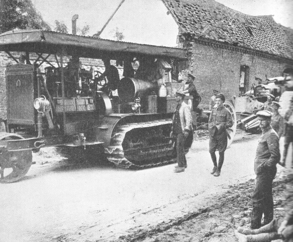 my favorite technique is working with the oils. In general most every surface gets some sort of treatment, with the purpose to either adding depth and interest to the base colors or to create a foundation for dirt and grime. Again, the same colors are used as were first established on the front wheel. And, my guess would be that these early tractors were probably required a lot of maintenance and upkeep, and thus a lot of opportunity for fuel and oil stains and spills. I used Ammo Engine Fuel Oil stains slightly thinned to create lighter effects, or mixed with a little black pigment fro create heavier accumulations.
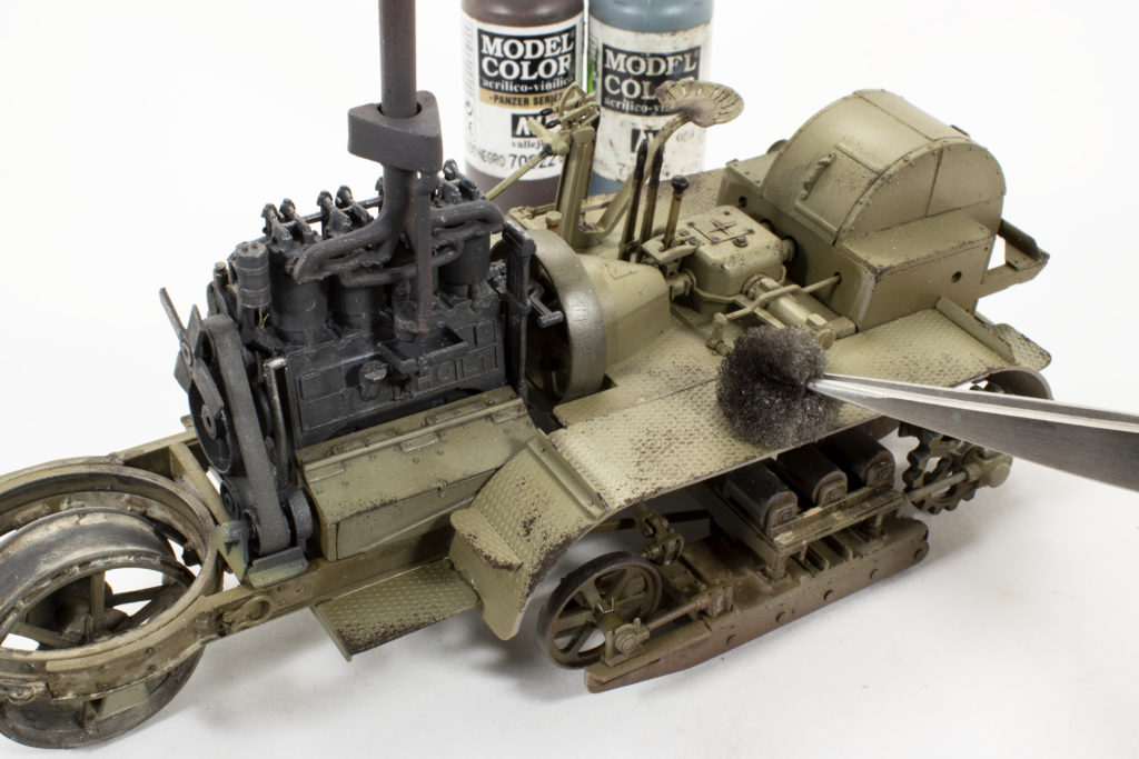
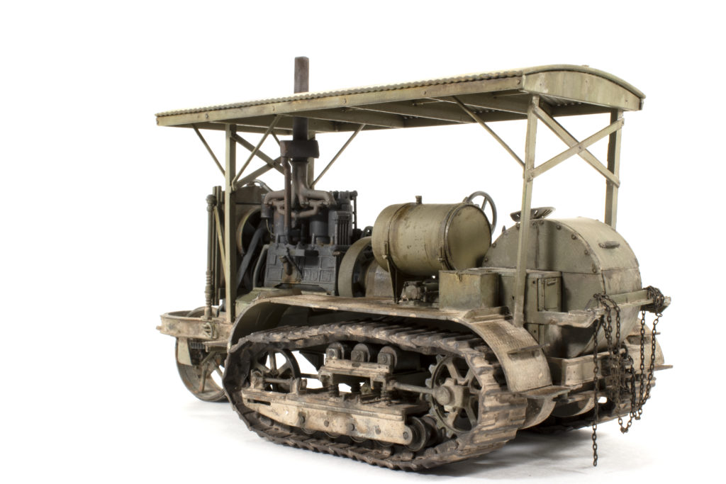
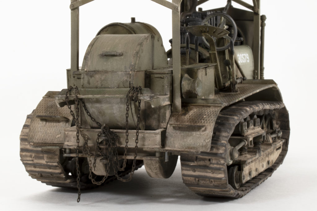
I had noticed on period photos that nearly all of the tractors had locker boxes mounted to the rear fenders. I initially resisted adding these because I was feeling lazy, but in the end, I went ahead and built a couple of boxes from plastic card, adding parts-box PE for 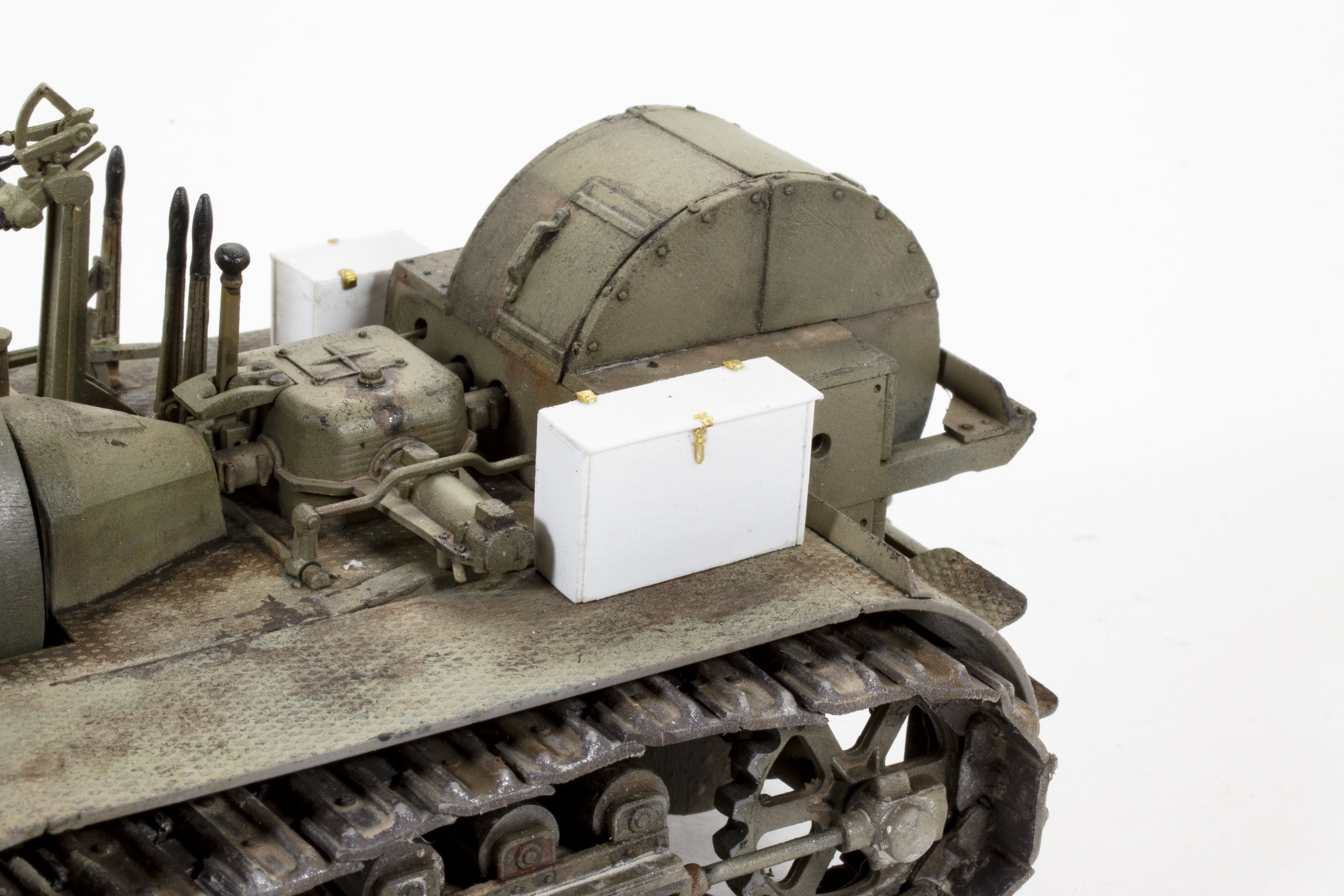 the latches and hinges. Also often seen were storage boxes with curved bottoms that sit further back on the fenders, I took the easy way out here and pretended I didn’t see those. Also notice that the tracks are on….and yes, they were a struggle.
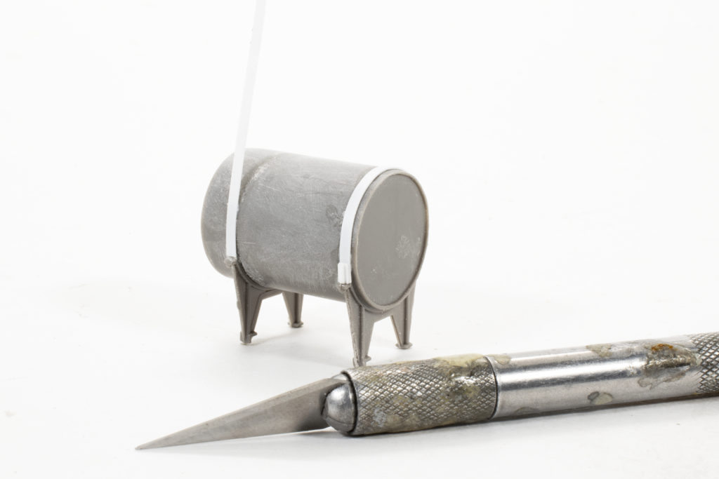
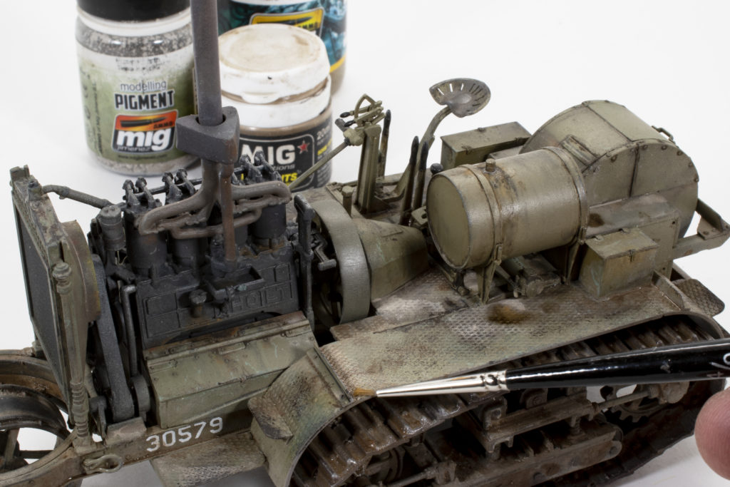
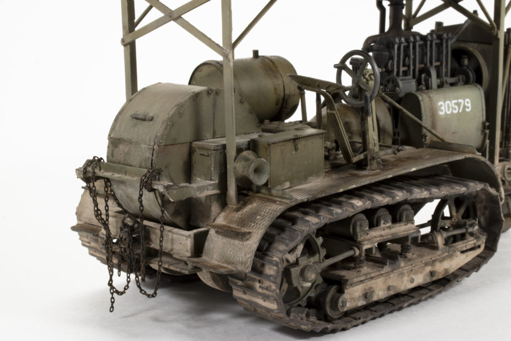
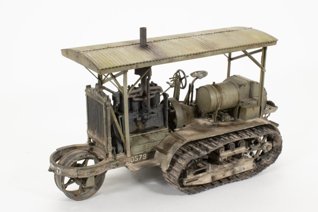
With the dirt and grime established with the oils, heavier accumulations were added using Ammo enamel products, primarily Light Soil Heavy Mud and Earth Effects. These were mixed together in varying ratios to create lighter (drier) areas and darker (moist) areas. One nice feature of the Ammo Heavy Mud effects is that they include an additive that, when dry develops a convincing texture 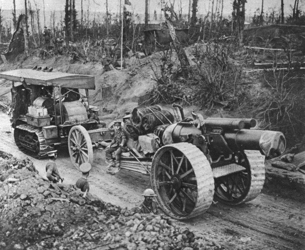 similar to pigments. The last feature to add is the large fuel drum that I brought up to the same level of weathering beginning with a light pin wash using Africa Korps Wash, followed by heavier fuel stains using oils and Oil and Fuel Stains mix. Final weathering includes adding pigments, especially to the lower running gear and in areas of higher accumulation. As usual for me, the pigments are mixed with thinner to a slurry type consistency and then applied by brush only to the targeted areas. I repeat this process until I am satisfied with the accumulations. Any excess or errant pigments can be removed using a dry, stiff brush.

![]()