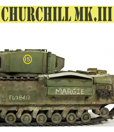
Churchill Mk.III “Margie”
 After the British Expeditionary Force had been evacuated at Dunkirk, having lost most of their equipment in the process, the British Army was in dire need of replacements. This was especially so for Tanks, of which there were only about 100 in the British Isles at that time. To accommodate this, the British government pushed forward a tank design that predated the onset of the Second World War, the A20.
The A20 was designed to meet the expected needs of First World War style trench warfare, where the main emphasis of the tank was to navigate shell cratered ground and demolish infantry obstacles such as barbed wire and was influenced that for the French Char B tank. Between then the Woolwich Arsenal and Harland
![]()
& Wolff developed the A20 from a specification in 1939 to working prototype form by June 1940. Once had been complete Vauxhall (the car manufacturers) took over the project, designing and building a prototype, which was designed the A22 by November 1940. The later version of tank had evolved based on the battles in Poland and France. However it still kept many of the same features that would put it a disadvantage confronted with the rapid nature of blitzkrieg tactics but were also prove to be some of its strengths. The first production units were available by the middle 1941.
![]() The hull was made up of simple flat plates initially bolted but later welded together. The suspension was fitted under the two large “panniers” either side of the hull – the track running over the top. There were 11 bogies either side, each carrying two 10-inch wheels. Only 9 of the bogies were taking the vehicle weight normally, with the front ones only coming into play when the vehicle nosed into the ground or against an obstacle. The rear ones acted in part as track tensions. The twin engines were connected through a common crankshaft feeding a regenerative transmission steered by a tiller bar rather than levers or steering wheel. The interior was comparatively roomy and the large hatches in the sides made escape easy. They were also to be one of the reasons for its later conversion into the AVRE. The first turrets were cast with a rounded shape – sufficient for the relatively small 2-pdr gun, but when a larger gun (6-pdr) was required the turrets became larger with welded construction. To fulfill its role as an infantry support vehicle the first models were equipped with a 3 inch howitzer in the hull and although this could deliver a useful HE round complementing the weakness of the 2-pdr in that area it was limited by a poor fire arc, due to the way the tracks extended in front of the hull.
The hull was made up of simple flat plates initially bolted but later welded together. The suspension was fitted under the two large “panniers” either side of the hull – the track running over the top. There were 11 bogies either side, each carrying two 10-inch wheels. Only 9 of the bogies were taking the vehicle weight normally, with the front ones only coming into play when the vehicle nosed into the ground or against an obstacle. The rear ones acted in part as track tensions. The twin engines were connected through a common crankshaft feeding a regenerative transmission steered by a tiller bar rather than levers or steering wheel. The interior was comparatively roomy and the large hatches in the sides made escape easy. They were also to be one of the reasons for its later conversion into the AVRE. The first turrets were cast with a rounded shape – sufficient for the relatively small 2-pdr gun, but when a larger gun (6-pdr) was required the turrets became larger with welded construction. To fulfill its role as an infantry support vehicle the first models were equipped with a 3 inch howitzer in the hull and although this could deliver a useful HE round complementing the weakness of the 2-pdr in that area it was limited by a poor fire arc, due to the way the tracks extended in front of the hull.
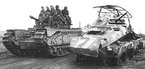
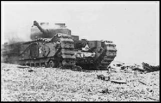 The hurried production in light of a possible invasion and lack of field tests meant that the tank entered service while still suffering from mechanical problems and defects. This meant that it performed poorly in its first combat outing, which was the disastrous raid on Dieppe in 1942. After numerous modifications, the tank did begin to see better performance in the North African Campaign though, where its exceptionally heavy armor, low silhouette and good climbing abilities gave it a reasonable degree of success. However, main complaints against it were that is was very low speed and had poor armament. These two weaknesses that would haunt it throughout its entire career, but after some modifications the Churchill tank served later in both the Italian Campaign and the Western Front.

|

|

|

|

|

|
Before beginning the kit construction in earnest I chose to chose add the AFV Club brass replacement bolt heads. These provide a little crisper detail as compared to the kit supplied plastic bolts. To install, holes must be drilled into the side panniers. Be mindful that the bolt pattern is slightly different from the left to the right side. I realized this just as I had completed drilling out one more hole than necessary. I fixed my mistake by gluing a small piece of plastic rod in the whole and sanding smooth.
There is no way around it, if you are going to build a Churchill then you are going to be dealing with an involved suspension and lots of road wheels. AFV has done some very nifty engineering with regard to the suspension assembly. The suspension itself is made up of about 50 parts per side and it should be noted that the suspension is designed to articulate upon real metal springs. Though not a difficult process, assembling the suspension does take some time. Many of the parts are not glued and it is a little tricky to keep everything in place while working on this area. When it did come time to put it all together as shown in step two of the instructions, I found it easiest to turn the panniers upside down until I was able to pinch the suspension posts between the two pannier halves. Once the two sides have been glued together the spring posts are securely held in place.
Finishing this area involves pacing the 11 suspension mounts and 11 mud scrappers. Do not be lulled to sleep during this stage, though many of the parts look may look similar on the sprue there are some differences. Be careful to study the instructions to insure that the parts are installed in their proper locations. Finally, the road wheels are attached to the suspension posts, and if everything has gone according to plan, the suspension will be workable. Nice touch.
The remainder of the suspension involves assembly of the drive wheels. Each wheel is in two halves with very crisp detail requiring very little additional cleanup other than the sprue attachment burs on a couple of the teeth. A vinyl poly cap trapped between the two drive sprocket halves for easy fitting to the drive axle. The final drive housing is also a separate part that is attached to the hull side plate with the idlers having two mounting panels attached to the front of the side panniers.
The main upper deck panel includes the forward crew hatch cut-outs, the turret ring and rear engine door cut-outs as well as separate front periscopes and ventilator dome. To the front of the hull, the crew hatches are shown with the correct offset. If you wished to display the hatches open the separate hatches have inner padding as well as very small separate etched inner fittings and plastic latch handle and separate outer grab handle for good definition. The driver’s plate has a separate main vision port hatch with the smaller bolted vision flap also separate so you can show either the full hatch or just to port open as was often the case. Additional smaller plastic and etched parts added to the hatch as well as the visor on the inside.

|

|

|

|

|

|

|

|

|

|
On the left is the co-axial BESA MG in full with an etched part for the jacket. On this point, the etched jacket and gun were a very tight fit into the mount (parts A32, A34, A35) and a little careful shaving was necessary to get the gun into position. Beyond that, work on the upper hull is straightforward and moves quickly with the only change I made was to replace the molded brackets on the pioneer tools with small bits of photo etch fret and wing nuts from the spare box.
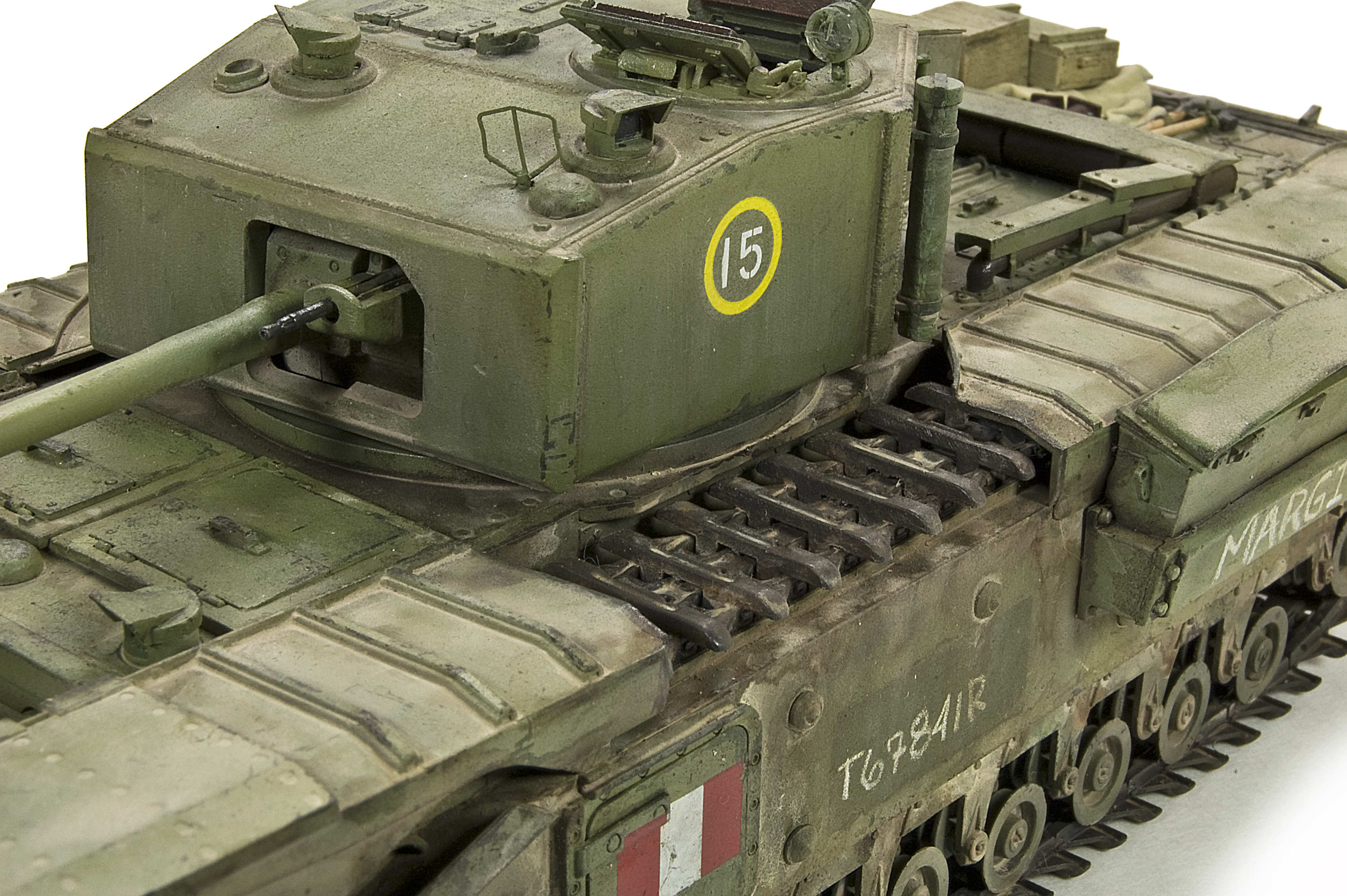
Moving on up we reach the turret. The 6pdr has the full gun breech inside as well as the full BESA co-axial MG the same as for the hull. The assembled gun breech fits to the back of the gun mantlet but I did need to trim the locating pin on the front of the breech a little to allow the metal barrel to fit. The gun assembly is held in place behind the front plate with two brackets allowing gun elevation.
The fit of the front and rear plates to the main turret shell is very good without the need for any trimming or gaps to be filled as is the lower turret ring making for a quick and easy assembly of the main turret parts. At the back is a three part turret box that goes together well and attaches to the four raised points on the rear turret wall. Smaller details round out the turret including a spot light, antennae posts, extinguishers and roof periscopes. As with the crew hatches, interior hatch details are provided for the commander’s hatch as well allowing them to be shown in the open position. A very delicate sighting frame is provided from using photo etch; I would suggest adding this item near the end of construction to avoid damage.
The kits comes with individual, track links and I must admit that the assembly of these links baffled me on the first attempts. I just could not get the knack of putting them together. They are designed so that one link hooks onto the next link, then locked into place by a top plate. On my early attempts I failed to place the top plate properly which caused the entire section to be mis-aligned, non-workable, and a general a mess. Frustrated with the entire process, I set the tracks aside overnight only to find that on my next days attempt they almost built themselves. Round two was quick and easy work taking about 1/2 hour per run. Hum, I think that there is a lesson in there someplace? The results are a nice, durable working track run that I believe really enhances the appearance of the kit.

|

|

|

|

|

|
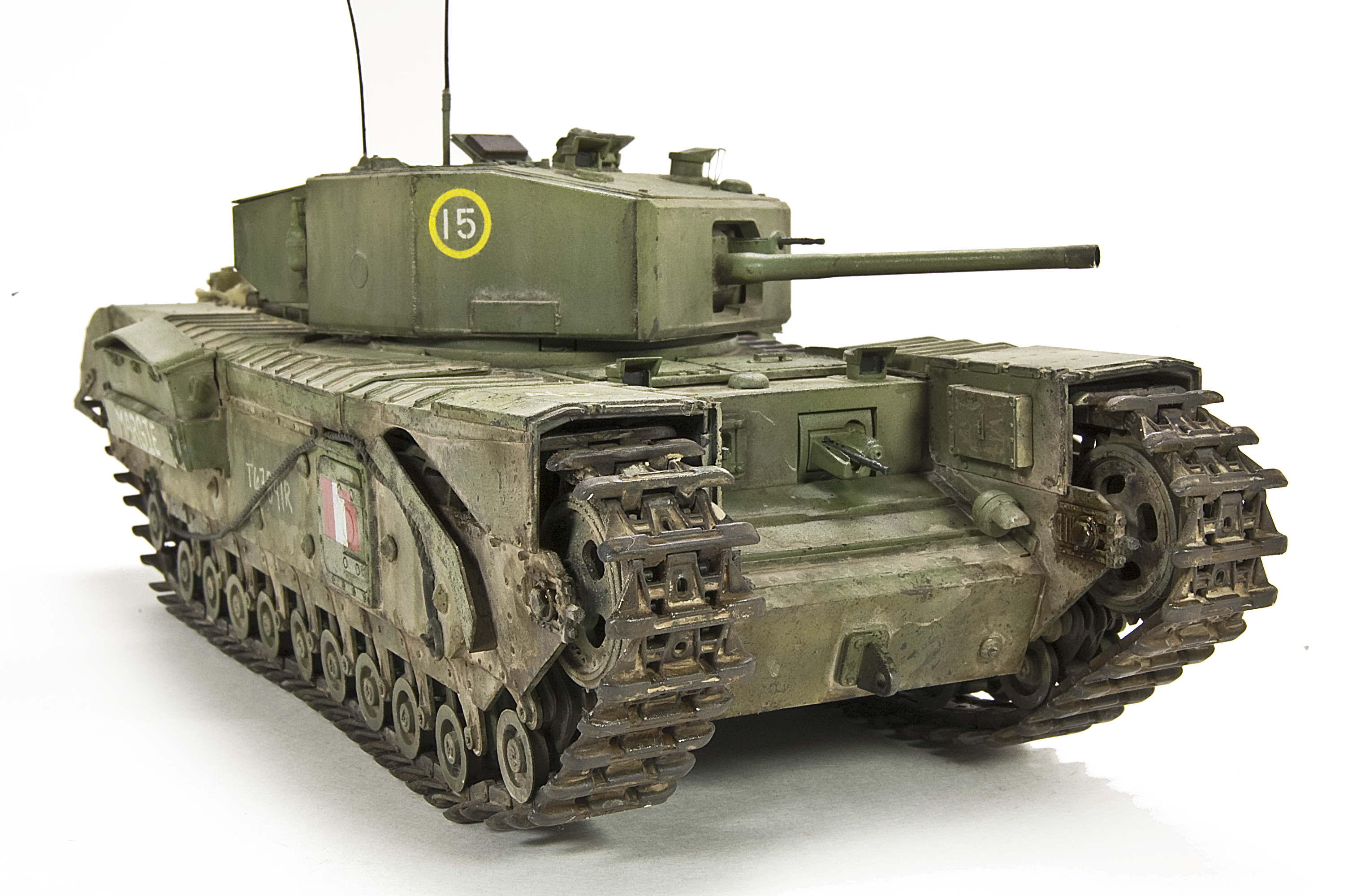
Adding the large track guards is the final task. These are presented in 6 panels, allowing the modeler to present his Churchill in any number of panel combinations from fully covered tracks to bare naked tracks. I chose partial nudity and decided to leave off the rounded front fenders and a section from the mid-left side. No particular reason, I just liked that look.
The first order of business in the painting process is a good primer of Mr. Surfacer. This product is great for giving a smooth, hard, durable base upon which to do my painting and finishing. I had in mind a vehicle serving in Tunisia, 1943. Sun fade, wear, and dirt will all be part of the fun. For me, single color vehicles are an excellent opportunity to create exciting finishes. I don’t believe that single colors (in this case green) need to be boring nor drab in appearance. I began with a base color using Tamiya XF-71 Cockpit Green and XF73 Dark Green/JGSDF sprayed in a light pattern over the vehicle. At this point I am not so much concerned with total, uniform coverage as I am actually trying to encourage variations in the finish. Although this base color seemed somewhat bright now, I wanted a color that was bright, and strong enough to stand up to the weathering that will come later.
As I proceed, I continue to look for opportunities to enhance shadows and light, contrast and brightness, all in an effort to lay an interesting foundation for the steps which follow. To this end, I added XF-14 J.A. Green to the base color and continued to lay foundation color. On certain features I used a small piece of cardboard as a mask, or template to highlight certain features. Finally, following some of the principals of the Color Modulation style, I add XF-4 Yellow/Green for the brightest highlights.
Next it’s time for getting down & dirty – worn & torn: Weathering. I feel that these opening steps are important to determining the “tone” of the finished project. As such, I am mindful to keep the wear under control and logical as you can always add more chips and scuffs later. To begin, using a fine brush and Vallejo colors (primarily German Camo Black Brown) I add small scratches and marks upon the vehicle. The brush is great for replicating scrapes and scratches in a very controlled manner. For variety, I then moved onto using small pieces of scrubbing pad to produce finer, more random chips and blemishes. Using a light touch and restraint are the keys to these steps.
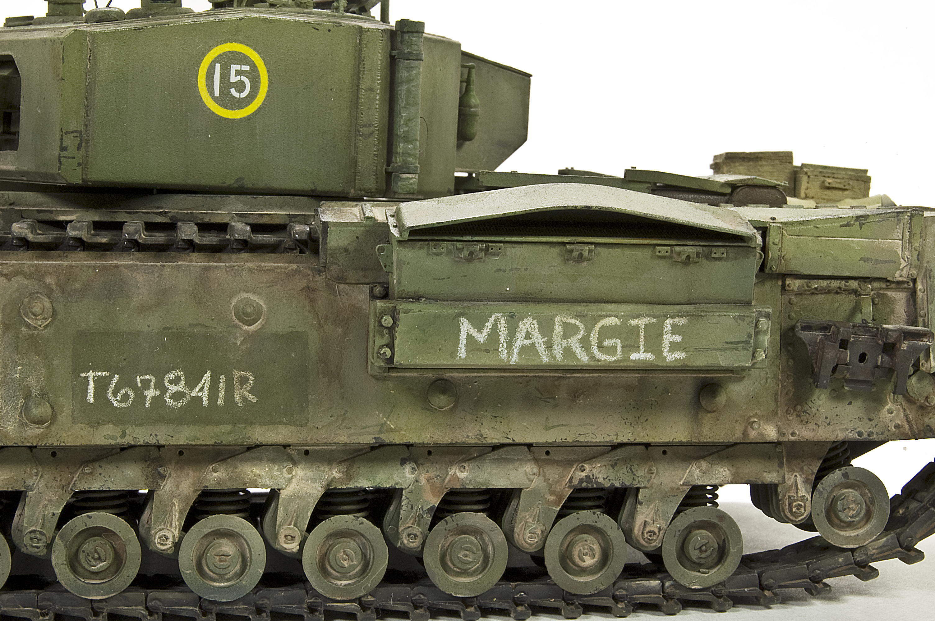
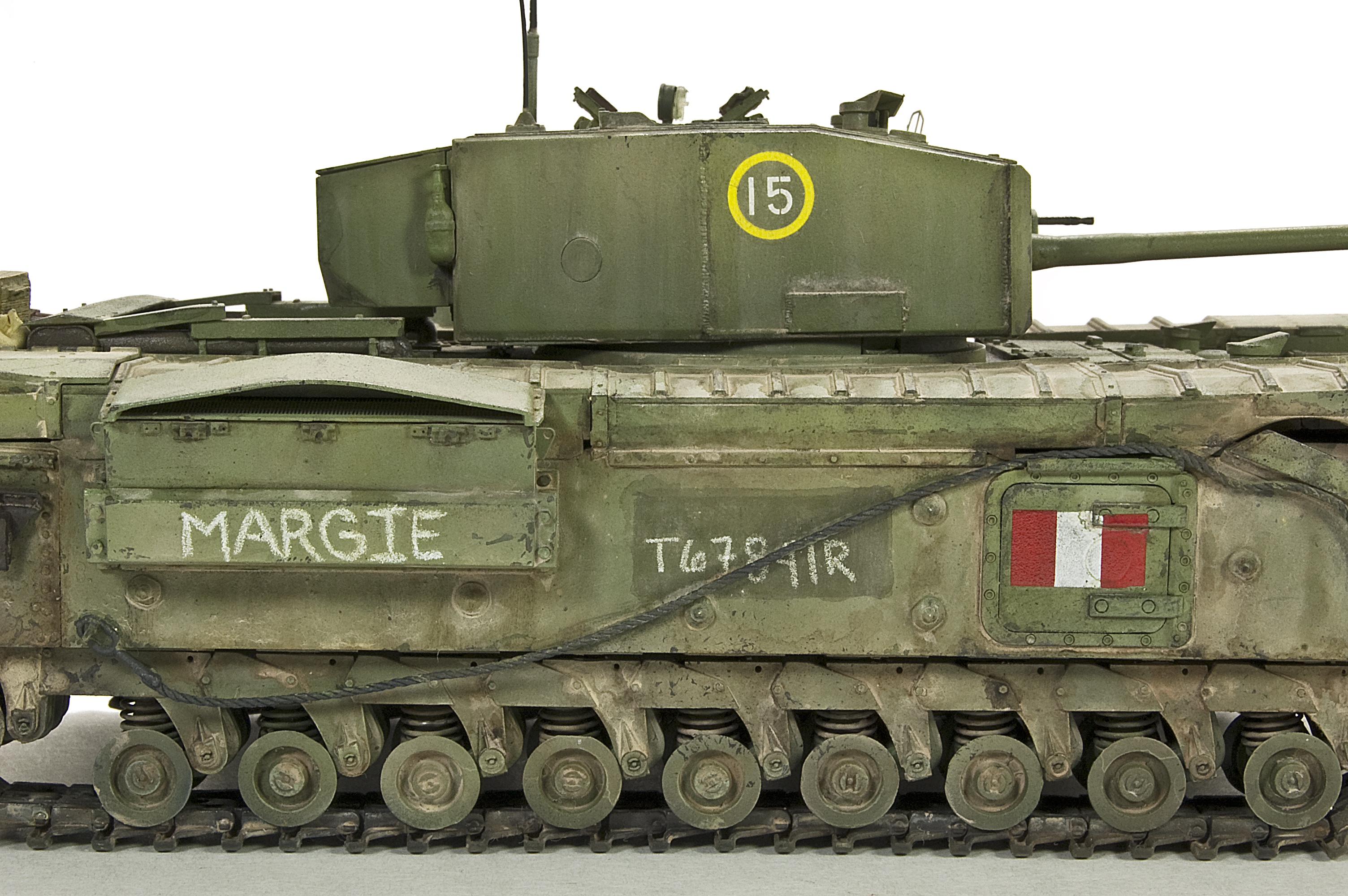
Lately, I am having a lot of fun working with, and developing ideas using acrylic filters. The filters are highly diluted colors applied to certain areas and features of the vehicle. I find them perfect for subtly altering and defining the vehicles’ features, fading paintwork, and begin laying the foundations for further weathering. During this stage I also decided to add a very personal touch to my Churchill by naming it MARGIE, after my wife. The name and vehicle numbers where created using a white Prismacolor pencil. Before adding the decals the entire vehicle was prepared for weathering by giving it a spray of Johnson’s Future acrylic polish. The decals on the turret are from the kit and were applied using a touch of Microscale Micro Sol, and then the entire vehicle was given another light mist of Future acrylic polish.
 After the acrylic I switch to using artist’s oils. Our Spanish friends call this “Adding Chromatic Richness, others call this Dot Fading. In my world it is really a little of each. Using colors such as the yellow ochre and green I am able to subtly alter the base color and give it more interest. Using lighter colors, such as white or creams will enhance the effects of fading. To apply, I pre-moisten the area with mineral spirits and then apply small dots of paints. On the horizontal surfaces I blend the colors using a scrubbing motion while the vertical surfaces receive a down stroke. This process can be repeated as necessary, but it is important to allow each layer to dry thoroughly before proceeding with the next. Earthen colors from the MIG range are used to lay a color foundation for the application of pigments to follow. As in all of these steps, numerous thin applications are used to create the effects. I am also very mindful to continually vary the color mix in order to enhance the visual interest.
The final component to the weathering mix is the application of MIG Productions pigments. I choose to apply my pigments “wet”, having first dissolved the in mineral spirits to the consistency of between muddy water and 1% milk. I find this to be a highly effective method which allows me to easily control the location and density of the pigments. As always, I continually adjust the color mix to add visual interest. Once the pigments have been applied, I will use a dry brush to lightly remove, or adjust the pigments in order to soften some of the edges. Once I have pigments applied to my satisfaction I permanently adhere them using MIG Productions Fixer. Touches of a loaded brush to the edge of the worked area, then just allow the Fixer to wash over the area. One nice thing about setting the pigments is that you are able to continue working the area once it has dried without disrupting your previous work.
Finally it is time to step back and take a look at what I have. One of the benefits of producing work for print is that I am continually taking photographs to journal the process. I have found the camera to be a very handy tool to really see what you have produced. The camera shows me in an unbiased manner what areas may need further refinement or attention. In this case I noticed that the vehicle did not seem unified between the hull and turret. Further work included applying a light wash of pigments to the turret and I also added a few extra pin washes to the lower hull in order to accentuate some of the details
|
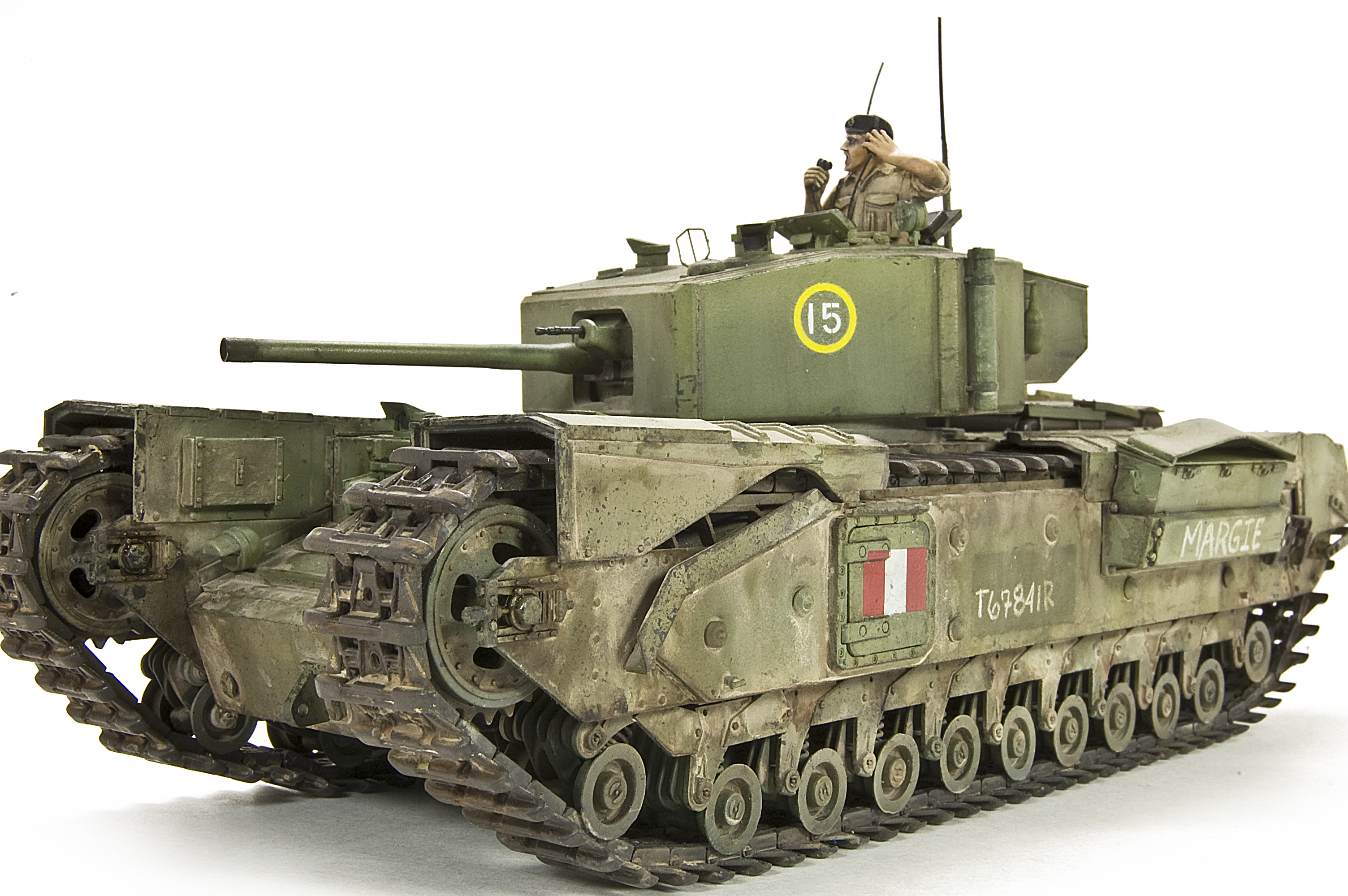

Although I have not presented this vehicle on a scenic base, I felt that a figure would be important to add a sense of scale to this monster. I found the perfect commander figure from the Ultracast range. The figure is perfectly cast in light resin with very little clean-up required. I painted him exclusively using Vallejo Model Color acrylics, then as a final touch I added the microphone and headphone cables made from thread coated with super glue.
This kit was a blast to build, pure and simple. Yes, the suspension is fiddly, but not so much so that it cast a cloud over the project, and the result is a superbly rendition of the complicated Churchill suspension. Adding the AFV Club replacement tracks certainly enhances the final appearance and is certainly worth the effort. I also very much appreciated the fact that AFV replicated the large track guards as separate pieces allowing the modeler an almost unlimited choice to add individuality to your vehicle. MARGIE has definitely found a place in my heart and on my shelf.